- 650 Cubic Inch 60° V-12 Engine -
A "Clean Sheet" Design
NOTE: All our Products, Designs, and Services are SUSTAINABLE, ORGANIC, GLUTEN-FREE, CONTAIN NO GMO's, and will not upset anyone's precious FEELINGS or delicate SENSIBILITIES.
CURRENT STATUS OF THE PROJECT (as of mid-June, 2020)
EPI no longer has any involvement in this engine project. Inevitable delays have occurred for a variety of reasons, resulting in conflict between EPI and the client. As a result, the Client-Contractor relationship has been severed by mutual agreement.
I am leaving these pages on the EPI website to describe the engine design details and technology for the general interest of our many readers.
ENGINE BACKGROUND
(NOTE: Previously, this page presented an overview of our V-12. As of 01 January, 2020, the
coverage has grown into 12 full web pages, covering in-depth design analysis of each major component.
THE TABLE OF CONTENTS IS AT THE BOTTOM OF THIS PAGE.
It is rare these days that a person has the chance to design a clean-sheet piston engine. Since mid-2009, I have been privileged to design two such engines – a 200 in³ air-cooled flat-four, and the 648 in³ liquid-cooled 60° V-12 that is the subject of this article.
In addition to doing the first build of both of those engines, I have seen the flat-four exceed its power target by more than 25% on the first full-power run, and under further dyno development seen that figure stretched to more than 30%.
This V12 project was originally conceptualized by the client as a one-off for his adventures in the air racing world. He conceived the engine as a replacement for the troublesome V12 found in many of the existing Thunder Mustangs. To be successful, the client estimated that he needed an engine that produced at least 1500 hp.
Figure 1 shows four Thunder Mustangs (the initial target aircraft) racing at the Reno Air Races. From front to rear, the pilots were: John Parker, Tom Gaston, Wayne Richards,and Brant Seghetti.
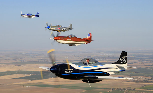
Figure 1: Racing at Reno--Photo Courtesy of Roger Cain Photography
The design, development and manufacture of this V12 has been funded and supported entirely by the client’s company, which has also provided outstanding machining and fabrication capabilities.
The client company has manufactured a large percentage of the major components for a complex engine (upper block, lower block, sump, accessory case housings, custom, CNC-finished heads, pistons, propeller and accessory drive gears, coolant pumps, torsional absorbers, valve gear components and more) and purchased the other necessary components (custom crankshafts, conrods, bearings, bespoke head castings, fasteners, cam followers, pushrods, valve springs, retainers, locks, etc.).
During initial discussions with the client, I suggested that, instead of doing a one-off for his plane, a V-12 such as he envisioned might match up with a need in the experimental aircraft engine world – a market that in the past has been offered several versions of ‘airworthy’ V12 engines made from cobbled-together V8 bits, resulting in V12 engines having 90° bank separation and generally flimsy crankshafts, which often manifest a variety of reliability issues.
A property common to these 90° block V12s is that they use some form of a custom crankshaft, with the rod throws separated by 120°. That arrangement results in an odd-firing 90°-30°-90°-30° sequence in which the cylinder that follows its predecessor by 30° actually blends with the preceding pulse to generate a nasty, sawtooth-shaped third primary order containing several complex harmonics.
That issue is covered in detail in my presentation of the Torsional Output of Piston Engines, which I would encourage the reader to examine and understand.
In stark contrast to that 90°-30°-90°-30° odd-firing arrangement, the V12 engines with a 60° block and a 120° crankshaft (such as the Rolls-Royce Merlin and Griffon aero engines; BMW, Ferrari, Maserati, Jaguar automotive engines, and many others) have even-firing sequences, in which each firing pulse is evenly separated from its predecessor and its successor by 60° of crankshaft rotation. It produces a very smooth sixth-order output signature with no torque reversals, and that sort of output waveform is much easier to attenuate before it reaches the next component in the powertrain – (again, please see Torsional Output of Piston Engines ).
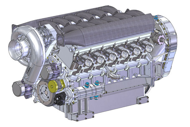
Figure 2: Supercharged Version of the EPI V12
As part of this discussion, it is interesting to note that the Audi diesel V12 that dominated Le Mans for several years was the 90° block / 120° crankshaft configuration. I once asked Audi Sport’s head of engine technology Ulrich Baretzky if the torsional signature of that engine caused any problems for the racecar driveline. He replied that in the case of his racecars, it was not a problem, but he declined to discuss the method of torsional suppression that he used.
However, that output signature has certainly proven to be a problem for powering an air propeller.
One of the better known 90° block V12 offerings uses a custom-cast block derived from a 400 in³ Gen-1 Small Block Chevrolet (4.125 x 3.750 inch bore / stroke on 4.400 bore centers with "siamesed" cylinders) with two cylinders added to each bank, for a displacement of 601 in³. That block carries with it the problems that arise from (a) a thin-walled 4.125" bore sleeve (liner) (b) pressed into a siamesed-bore aluminum block having 4.400-inch bore spacing, (c) leaving only 0.275" (minimum) of material between adjacent cylinders. The space between adjacent cylinders in such a design must contain (a) two cylinder sleeves that are suitable for the combustion loads applied, and (b) the supporting aluminum structure for those sleeves.
In any composite structure in which there is a substantial difference between the elasticity modulus of the two materials, the material with the higher stiffness will end up carrying the majority of the stress unless there are design compromises made to increase the load-bearing area of the less-stiff material.
Knowing that the modulus of steel is almost 3 times greater than that of aluminum, then if the steel sleeves are 0.090 thick at the top, that leaves a minimum cast-aluminum wall of 0.095 between cylinders, which clearly means that the steel liners carry the preponderance of the combustion loads.
Further, with only 0.275 between the cylinders, head gasket sealing becomes a major problem under high combustion loads. And siamesed cylinders (cylinders physically attached to the adjacent cylinders) prevent the proper circulation of coolant, which is very important in preventing auto-ignition problems at high cylinder pressures, made worse by the significant heating of the incoming charge caused by a customer-added, not-very-efficient radial compressor with no aftercooler.
There are also well-known problems with the dry-sump lubrication system in that engine. The lower block (saddle) is tapered in such a way that it pushes the windage oil toward (instead of drawing it away from) the rotating components, producing a whirling aerated mess of lubricant that the scavenge pumps cannot grab.
The scavenge system is apparently just-barely-adequate for a naturally-aspirated engine, but with any form of boost added to the engine, the increased crankcase pressure pushes the poor scavenging system over the edge. I have seen instances in which a boosted engine pumped the oil tank dry in a few seconds of high-power operation and all the oil (MANY quarts) ended up in the "dry" sump (and of course oil pressure went to zero.)
That engine uses an extended 6-cylinder version of the Chevrolet ‘splayed valve’ head, which was a notably good performer - in its generation.
The crankshaft in that engine is a bespoke 120° billet steel production, with the conrod oiling holes drilled the wrong way for a crankshaft that rotates counterclockwise (viewed from the cam drive end). As mentioned above, the output of that 90° block / 120° crank° V12 engine contains the harsh third-order sawtooth excitation (described in THIS ARTICLE) which has, in several known cases, deteriorated the propeller gearboxes to the point of near-destruction.
The propeller gearbox was copied from a previous Big-Block Chevrolet V8-based ”aircraft” engine that has been plagued with reliability issues in that V8 (4th order excitation) application. That gearbox fares even worse in the 90° block / 120° crank V12 application, with its harsh torsional signature of a third-order sawtooth waveform.
Tthe accessory drive on that engine is an eyebrow-raising serpentine belt arrangement that has failed in-flight on several occasions. I have no doubt that the odd-fire torsionals, imposed on the free end of the crankshaft, play a role in those difficulties.
It was the sum of those and other factors that enabled me to convince my client that a reliable high-performance 60° V12 power plant (engine with a well-designed, integrated propeller gearbox and gear-driven aircraft accessories) could be a worthwhile and expanding marketplace by virtue of being a near-bolt-in for many of the replica warplanes.
After an extensive set of simulation studies to determine reasonable performance criteria, we settled on three variations of the base V12 engine.
The first is a naturally aspirated version that will produce 810 bhp at 4800 RPM (but not with the short exhaust stacks shown in the preceding pictures). The second is a gear-driven-supercharger version, which provides the “authenticity” required by certain builders for replica WWII aircraft engines, and is expected to produce about 1225 hp at 4800-5000 RPM with a reasonable boost level and good aftercooling. The third is a heavily turbocharged-and-aftercooled race version that is expected to produce more than 1750 hp at 6000 RPM.
Whereas the targeted life expectancy of the first two versions is 2000 hours (achieved by the best contemporary aircraft engines), the turbocharged race version will have a much lower – but still reasonable – life expectancy.
The remainder of this presentation will cover the conceptualization, simulation studies, component design, detailed structural analysis (FEA), manufacturing, and prototype construction of this engine project. I have divided it into eleven separate pages in the interests of clarity and organization (and to avoid causing the reader to lose interest). The series might be a reasonable Introduction to Engine Design course..
Series Table of Contents
