Part 1: New V12 - Design Constraints
Requirements, Goals, and Overview
NOTE: All our Products, Designs, and Services are SUSTAINABLE, ORGANIC, GLUTEN-FREE, CONTAIN NO GMO's, and will not upset anyone's precious FEELINGS or delicate SENSIBILITIES.
NOTE: EPI no longer has any involvement in this engine project. Project delays have occurred for a variety of reasons, resulting in conflict between EPI and the client. As a result, the Client-Contractor relationship has been severed by mutual agreement.
I am leaving these pages on the EPI website to describe the engine design details and technology for the general interest of our many readers.
The requirements for an aircraft power plant are quite different from those commonly encountered by race engine designers. My view of the top four requirements for an aircraft engine, in order, is (1) reliability, (2) weight, (3) power and (4) cost.
First and foremost, an aircraft engine must be reliable. Naturally, that reliability will be quantified differently for an engine that is expected to survive one or two hours of extreme full-power operation (as in the Reno Air Races for example) than for an engine that will be expected to survive 2000 hours, most of which is at 75% of full power, with extended periods of operation at full power.
We have opted for a design that can be expected to operate reliably for more than 2000 hours while delivering over 1200 hp, and having reduced (but still excellent) reliability while delivering in excess of 1750 HP continuous. Those performance targets will be proved (or disproved) during testing.
In opposition to the reliability criterion, it is highly desirable for an aircraft engine to be lightweight. There is no point designing an aircraft engine that produces very high output with extreme reliability if the specific weight is 3 lb/hp (a figure better suited to locomotive duty).
Naturally, high power output is a prime goal, which also runs in opposition to the reliability criterion.
Lastly, cost must be contained so that the product is affordable to the intended marketplace. The “government-funded-flagrant-waste-and-corruption ” cost model definitely does not apply here. However, low cost often runs in opposition to the other three criteria. Design almost always requires compromise.
When the initial engine discussions occurred, the existing rules for the Reno Air Racing Association Sport Class required a single piston engine with a displacement of no more than 650 in³. That was what established the displacement criterion for this engine.
The Sport Class rules have subsequently been changed to allow one or more piston engines, having a total displacement of no more than 1000 in³. There is now at least one twin-engined aircraft in the Reno Air Race design pipeline, but overcoming the additional drag imposed by two power plants is a major challenge, which has been demonstrated on previous Reno aircraft.
The V12 presented here is a 648 in³, 60° vee pushrod engine with a custom aluminum billet block, high-strength wet steel liners, custom box-bridged pistons, a very stiff and fully counterweighted billet crankshaft, and custom designed two-valve-per-cylinder heads.
This V12 engine has a torsionally isolated, geared accessory drive section that provides redundant coolant pumps, redundant alternators, an instrument vacuum pump, and a hydraulic pump for the landing gear. The accessory drive also includes (when needed) a geared, torsionally-isolated 150 hp capacity supercharger drive.
The engine uses electronically-controlled fuel injection and ignition, with an intake system tuned to locate the engine torque peak for optimal performance in range between takeoff and cruise rpm.
The fully integrated, torsionally-isolated propeller reduction gearbox has a continuous torque input capacity of more than 1750 lb-ft and ratios ranging from 1.72 to 3.16.
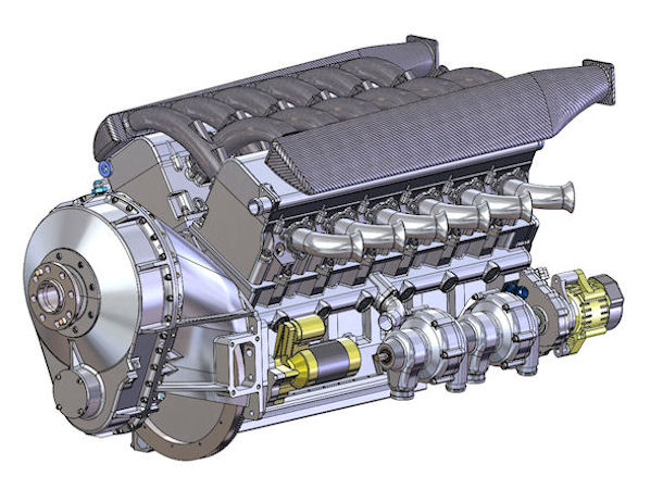
Figure 1: Front View - EPI V12
The engine ‘block’ consists of two major components (upper and lower), which are split on the horizontal centerline of the crankshaft. The upper half contains the two cylinder banks (separated by 60°), the steel cylinder liners, the single camshaft, hydraulic roller lifters, lubrication and coolant galleries, piston cooling jets, accessory drives and the upper main bearing halves.
The lower half (the ‘saddle’) extends well below the crankshaft centerline and becomes a fully structural component when torqued in place. It contains the lower main bearing halves and a portion of the oil sump system.
Early in the design discussions, one of the main topics was whether to make this a four-valve OHC design, like the Merlin / Griffon. I resisted going in that direction because it was clear to me that (a) such a layout would occupy far too much volume (height and width) to fit within the targeted vehicle engine compartments, and (b) it would add a lot of unwanted and unproductive weight to the final product. (Picture the morbidly obese 5.4 liter Ford SOHC and DOHC ‘modular’ V8 next to the compact and svelte GM two-valve pushrod LS 6 and 7 liter V8 engines.)
The following three pictures show what a tight fit the naturally-aspirated version of the engine (in pushrod-OHV form) is inside the cowling of the target P-51 80% scale replica. The Supercharged and Turbocharged versions are even more snug.
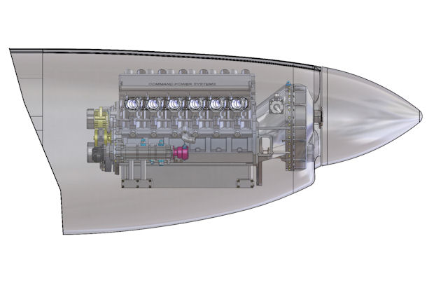
Figure 2: EPI V12 Installation Side View
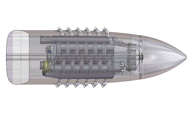
Figure 3: EPI V12 Installation Top View
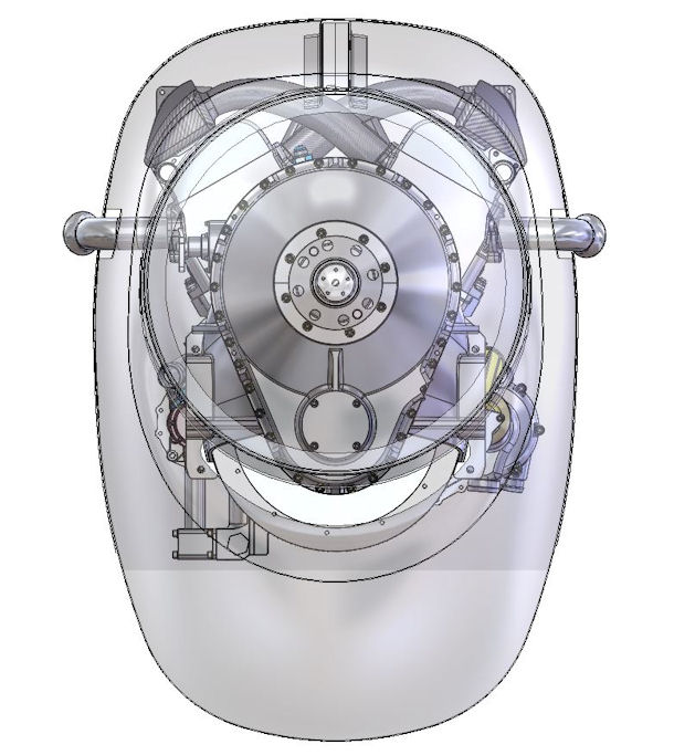
Figure 1: EPI V12 Installation Front View
Because the operating range of the race engine version is limited to about 6000 RPM by propeller and gearbox constraints (as described below), the two-valve pushrod compromise does not restrict the performance nearly as much as it might if the operating speeds were higher, where the four-valve layout becomes a bigger advantage.
From my NASCAR race engine experience, I knew that a well-engineered 358 cubic inch, two-valve, naturally aspirated pushrod V8 with a modified wedge two-valve combustion chamber, non-coplanar and slightly canted valves, feeding through a single centrally located throttle body, would reliably produce over 890 BHP (prior to the moronic NASCAR 2015 “tapered spacer ” legislation), more than 15.5 bar of BMEP at a very high mean piston velocity, and could operate at maximum power and high RPM (over 9000) for several hours without any major power loss.
My work with some of the NASCAR Cup engine companies has enabled me to draw from this technology base, and our simulation-supported 14.5 bar of naturally aspirated BMEP – based on actual cam profiles, port flow curves, cylinder pressure traces, etc. – is a realistic design target consistent with the other design constraints.
The upper limit of 6000 engine RPM for the turbocharged race version came from the combined limitations of the available gearbox ratios and the propellers that are available for that level of power and the anticipated vehicle speeds.
Propellers that can absorb 1800 hp and operate efficiently at well over 400 mph typically have a limit of about 1900 RPM, depending on the specifics of the propeller and the operating conditions
(For a complete explanation of the constraints imposed by a high-powered propeller operating at high airspeeds, see Propeller Performance.)
To maintain some degree of weight, size and cost control, the gearbox is a single-mesh design. The maximum ratio that will fit into the gearbox housing that would comfortably fit into the target aircraft design envelope is 3.16.
So with a maximum propeller speed of 1900 RPM and a maximum gear ratio of 3.16, 6000 RPM becomes the maximum available crankshaft RPM for this application.
The combination of a piston engine driving a reduction gearbox driving a propeller while coupled by flexible components to a non-rigid vehicle (airframe) is the very incarnation of a complex vibratory system, so the issue of vibration had to be addressed from the outset. In addition, the gearbox would have to sustain input torque values exceeding 1600 lb-ft at 6000 RPM.
However, the torque input is only one of the load requirements. The reduction gearbox must also support massive propeller thrust loads in both directions, plus the bearing loads produced by gear meshing forces, plus extreme gyroscopic bending moments caused by deflecting a massive whirling propeller in the pitch or yaw axes. Aviation history is full of stories of ill-conceived and / or poorly designed propeller gearboxes self-destructing early in their operation.
Regarding weight, it is remarkable that contemporary metallurgical science and FEA have made it possible for a 4.185 inch diameter, 400 gram aluminum piston and a 525 gram steel conrod (NASCAR Cup minimum weights) to survive up to 9400 RPM continuous at nearly 2.5 hp per cubic inch – for hours. The designs and components developed by NASCAR Cup engineers provided major inspiration towards the lightweight-yet-robust targets we have achieved.
The naturally aspirated, dry-sump version of this engine weighs just over 880 lb, including (a) the propeller reduction gearbox with propeller governor and torsional isolation system (more than 110 lbs.combined), (b) geared accessory drive with (c) twin coolant pumps, dual alternators, instrument vacuum pump, and hydraulic pump for operating the landing gear. The complete wet-sump version, without the hydraulic landing gear pump, weighs just under 800 pounds.
Traditional aircraft engine design has not been particularly troubled by cost constraints, since most such projects have been funded by governments. However, the government cost model was not appropriate here, and every effort has been made to achieve a design in which the costs are contained while at the same time being able to maintain the required standards of quality and repeatability in the manufacture of components.
Trade-offs were made in favor of reliability – stiffness, strength, materials with high endurance limits, and high natural frequencies where advantageous (except in one instance described later in the gearbox details), but off-the-shelf components were used whenever it was possible to satisfy those constraints with high-quality purchased components instead of custom-manufactured ones.
