
- Propeller Performance Factors -
Basic Information to Help Select the Correct Propeller
NOTE: All our Products, Designs, and Services are SUSTAINABLE, ORGANIC, GLUTEN-FREE, CONTAIN NO GMO's, and will not upset anyone's precious FEELINGS or delicate SENSIBILITIES
The in-flight performance of a propeller encompasses several complex subjects. The high-performance propellers that are available these days are the product of a lot of engineering, development, testing – and unfortunately a few mistakes.
The selection of an appropriate propeller for a new aircraft should not be done without considering several factors which characterize the performance of a propeller.
The following sections of this page present a few basics to help provide a better understanding of propeller performance.
CONTENTS
1. BACKGROUND
2. THRUST, POWER, and EFFICIENCY
4. ENGINE POWER vs AIRFRAME DRAG
BACKGROUND
The purpose of a propeller is to convert engine power, delivered to the propeller by a rotating shaft, into a quasi-linear thrust force, and to do so as efficiently as possible throughout a suitable range of vehicle velocities. The propeller generates thrust by accelerating a large mass of air from a lower velocity (in front of the propeller disc, roughly the current speed of the vehicle) to a higher velocity behind the propeller disc
A propeller blade is a sophisticated whirling airfoil. At a constant propeller rpm and vehicle true airspeed, the relative velocity of the air (and therefore the airfoil’s angle of attack) varies with the distance along the blade from the propeller’s center of rotation.
Therefore, in an effort to provide an ideal angle of attack along the entire blade, the blade has a "twist" to it which varies the pitch angle of the blade from the low (at the root) to high (at the tip), using various distribution algorithms derived from extensive experimentation and development.
The nominal pitch angle of a blade (β) is typically the angle measured at 75% of the radial distance from the center of rotation to the propeller tip.
At a constant propeller rpm, as aircraft velocity increases, the angle of attack seen by the propeller blade of a fixed-pitch propeller will obviously decrease. That limits the maximum efficiency of a fixed-pitch propeller to a single airspeed at a given rpm, as shown in Figure 1 (from ref-4:13:149)..
This graph is a representative plot of propeller efficiency at different blade pitch angles (β) and advance ratios (speed). The Y-axis of that plot is propeller efficiency (how efficiently the propeller converts the applied engine power into thrust (discussed later), and the X-axis of the plot is “Advance Ratio”, which is a non-dimensionalized quantification of propeller speed parameters, calculated as follows:
Advance Ratio = true airspeed {ft/sec} / (propeller speed {rev/sec} x diameter {ft})
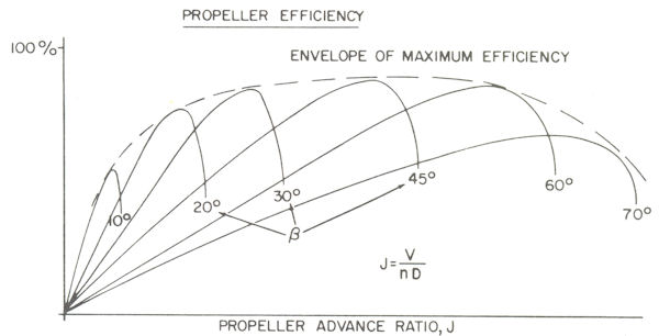
Figure 1
The curves in Figure 1 demonstrate that the speed range over which good propeller efficiency can be achieved is very limited for a fixed pitch angle. It is also clear from that plot that if the blade pitch could be varied in flight, the propeller efficiency could be quite high over a wide range of operating conditions.
In fact, that variable-pitch capability is common to all high-performance propellers, and is most often accomplished by a hydraulic piston mechanism in the propeller hub. Axial movement of that piston changes the pitch of the blades. A mechanical governor varies the hydraulic pressure that is applied to the piston in response to (a) instantaneous propeller rpm, and (b) pilot command.
That system allows the propeller governor to maintain propeller rpm at a pilot-requested value (within certain limits) by suitably adjusting the propeller load (blade angle) in response to either a change in engine power or a change in aircraft flight conditions (or both).
There are other pitch control mechanisms as well, which attempt to accomplish the same task, but this is the most common system.
THRUST, POWER and EFFICIENCY
As described above, a rotating propeller produces thrust, which is not power, it is a force that is applied to the airframe.
Power is defined as work per unit of time, which is force x distance / time. One horsepower is defined as 550 ft-lb of work per second, so the propeller power that is produced equals thrust (pounds of force) multiplied by velocity (distance per unit time) and a scaling constant appropriate to the unit system being used (550 in this case).
So using the pounds, hp and feet-per-second unit system:
Propeller (propulsive) hp = thrust {lbs} * velocity {ft/sec} / 550
Rearranging that equation to solve for thrust, produces:
Thrust = 550 * propeller hp / velocity
That equation shows why, for a constant amount of engine power, the thrust generated by a propeller MUST decrease with speed; - - - speed is the denominator in the above equation, so as speed increases, the quotient (thrust) must decrease.
Propeller efficiency is defined as power produced (propeller power) divided by power applied (engine power).
propeller efficiency = propeller power (produced) / engine power (applied)
OR
propeller efficiency = thrust {lbs} x velocity {ft/sec} / (engine power {hp} * 550)
In case you are wondering, multiplying "engine hp" by 550 produces the number of ft - lb per second in that number of hp, so as to match the units in the numerator of the equation (8th grade algebra).
The general relationship between engine power, thrust, and propeller power across a given speed envelope in a constant atmospheric model is shown in Figure 2 below. The red line shows a constant engine power at all speeds. The green line shows how much of that engine power is converted into propeller power (propeller efficiency x engine power), and the purple line shows how thrust varies with speed and propeller efficiency, first rising very quickly with as speed increases (a result of the very high slope of the efficiency curve), then decreasing as speed increases.
Note that the green line is also a clear depiction of the overall efficiency envelope of the propeller at the specific power loading shown, since engine power in this graph is a constant.
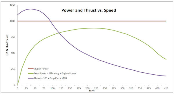
Figure 2
Again, the purple curve illustrates the rapid rise in thrust due to the fact that at low airspeeds, propeller efficiency is very low. As airspeed increases, so does efficiency, quickly at first, then more slowly, up to its maximum (about 85-87%), and then falls off beyond the peak That trend is also shown by the outline of the Maximum Efficiency Envelope in Figure 1.
The following plot (Figure 3) illustrates that effect again by showing the thrust generated by a typical propeller with different levels of constant engine horsepower applied to it, as a function of airspeed (15 through 240 MPH) and power applied to it (250 through 500 HP).
Note that the rising slope of the thrust curves at very low airspeeds is a by-product of the fact that efficiency is very low at low airspeeds, but increases fairly rapidly as airspeed increases, as discussed above. That will become more clear as we present more information on propeller efficiency below.
Figure 3
Now, some more simple algebra enables the production of some efficiency equations that are a bit more useful.
As presented above Figure 2:
propeller efficiency {"eff"}= (thrust x velocity) / (engine hp x 550)
There is already the constant "550" in that equation (550 ft-lb / sec in one HP), so instead of having to convert airspeed (typically MPH or Knots) into feet / second, I simply combine the conversion factors to produce:
eff = Thrust x Speed {KTAS or MPH} / (Engine HP x "K" )
(where "K" is a constant to account for units).
If the system of units is Pounds (thrust), Horsepower (power) and Knots True Airspeed (KTAS), then the equation becomes:
eff = ( Thrust x KTAS ) / ( HP x 326 )
In any of the following equations, if you prefer to use MPH-Ttue Airspeed (MTAS) instead of KTAS, use the constant 375 in place of 326. For example:
eff = ( Thrust x MTAS ) / ( HP x 375)
The equation for efficiency has other useful forms. Rearranging the terms, the equation for the thrust produced at a known airspeed, engine power, and propeller efficiency yields:
Thrust = ( Engine HP x eff x 326 ) / KTAS
To find the HP required to produce a known thrust at a known airspeed and propeller efficiency:
Engine HP = ( Thrust x KTAS ) / ( 326 x eff )
To find the speed which can be reached with a known engine HP, prop efficiency and airframe drag (thrust = drag in steady state level flight):
KTAS = ( Engine HP x eff x 326 ) / Drag
Those equations are helpful when using a propeller performance map (explained below).
In general, the larger the propeller diameter, the more efficient it will be. The following three equations (ref-4:9:219) provide an estimate of the recommended propeller diameters (inches) as a function of the horsepower available to the prop. ("Fourth root" is the square root of the square root.)
Two-blade: d = 22 x fourth root of (HP)
Three-blade: d = 18 x fourth root of (HP)
Three-blade (agricultural application): d = 20 x fourth root of (HP)
However, the maximum useful prop diameter will be limited by the speed of the propeller tip and by the airframe-provided ground clearance.
PROPELLER TIP SPEED
As described above, variable-pitch propellers are highly efficient over a wide range of airspeeds and applied engine power. However, that performance has important limiting parameters.
Anytime the aircraft is in motion (and the propeller is turning, of course), the path of the tip of a propeller blade through the air is a helix, and therefore, it's velocity (the "tip speed") is the vector sum of the rotational velocity plus the translational velocity, or the helical tip velocity (explained in detail below).
Maximum helical tip velocity is an important parameter for propeller selection. In the absence of specific data from the manufacturer, it is safe to assume that (a) the maximum propeller efficiency will be about 85% to 87% (for any propeller a non-governmental agency can afford), and (b) that the propeller efficiency begins to decrease dramatically when the propller is operated at a helical tip velocity greater than the peak efficiency Mach Number, which can vary from about 0.84 to 0.88 M. (Mach Number is the ratio of a specific velocity to the local velocity of sound, explained below.)
The very best contemporary propellers can approach 90% peak conversion efficiency, but with any propeller, the efficiency drops very rapidly as the tip velocity exceeds its optimal value. The loss of efficiency occurs because the local air velocity over the surface of the propeller blade (near the point of maximum chordal airfoil thickness and velocity) will reach Mach 1, and create a shockwave that separates the airflow from the surface and dissipates propeller energy.
That phenomenon is very easy to spot in a high speed aircraft which has the capacity to run the propeller too fast for a given set of flight conditions. Here is an example. A few years ago, I was flying the facrtory Glasair-3 to an airshow. I was cruising at 13,000 feet, 2400 RPM, wide open throttle. I was running a bit behind schedule, so in pursuit of a few more knots, I decided to operate at max power (2700 RPM, WOT). It was something of a surprise when I lost about 15 knots of airspeed. I set the RPM back to 2400, and regained the lost 15 knots. Later I did the calculations to verify that the loss was due to the sudden loss of propeller efficiency. It was.
It is actually quite simple to do the arithmetic necessary to determine the tip Mach of a prop at a given RPM and true airspeed. First, calculate the helical tip velocity components (rotational velocity, Vr, and aircraft forward velocity, Va).
The rotational velocity is the diameter of the prop times the RPM times a conversion factor. Again using KTAS as the unit of speed, the rotational velocity in feet per second is:
Vr (ft / sec) = RPM x Prop Diameter (inches) x 3.1416 / (12 x 60), OR
Vr (ft / sec) = RPM x Prop Diameter (inches) / 229.2
The forward velocity is simply the aircraft TAS expressed in feet per second, or:
Va (ft / sec) = KTAS x 6076 / 3600 or Vt = KTAS x 1.688
With the rotational and translational speed (in the same units, of course) you can easily calculate the helical tip speed:
Vht = square root ( Vr² + Va²)
Next, calculate the speed of sound (Mach 1.0). The speed of sound in air varies with the square root of absolute temperature ONLY, as defined by the following equation:
M1 = square root (k x g x R x T)
where k, g and R are constants (1.4, 32.17 and 53.34 for air)
and T is the absolute temperature (°F + 460) of the surrounding air.
For example, if you are at 13,000 feet on a standard day, the air temperature is 12.71 °F. So the speed of sound (in feet per second) is:
M1 = square root ( 1.4 x 32.17 x 53.34 x (460 + 12.71) )
M1 = 49.013 x square root ( 472.71 ) = 1065.6 ft / sec.
The Mach number of a given speed is simply the ratio of that speed to the local value of Mach 1, or:
Mn = speed / M1
Putting it all together in a specific example, suppose you are flying at 13,000 feet on a standard day at a true airspeed of 240 knots and an 84-inch propeller turning at 2700 RPM. Here is how to calculate your prop-tip Mach (using the simple equations above):
Vr = 2700 x 84 / 229.2 = 989.5
Va = 240 x 1.688 = 405.1
Vht = square root ( 405.1² + 989.5² ) = 1069.2 feet per second
Tip Mach = 1069.2 / 1065.6 = 1.034
See why the Glasair slowed down?
Now, to calculate the RPM at which a known tip mach occurs on your propeller, perform a bit of simple algebra on those four equations (Vr, Vt, Vs1 and M) to solve for RPM with a given Propeller Diameter, TAS, and outside air temperature.
(Instead of doing the calculations by hand, it is very convenient to put the equations into an Excel spreadsheet and let your computer do the arithmetic. The computer is much faster at it that you are, and probably more accurate too.)
PROPELLER PERFORMANCE MAPS
Propeller performance maps are 3-dimensional tables which list the efficiency of a propeller at various combinations of advance ratio and power loading for various altitude conditions. Most propeller manufacturers characterize the performance of each of their products with such a performance map. Don't be afraid to ask your propeller manufacturer for a map defining the propeller (s) you are considering or evaluating.
By using the appropriate map, you can accurately determine the operating efficiency for almost every condition (as long as map data represent the actual performance of the prop, which is not always the case ! ).
In order to use a performance map, you will need to calculate the advance ratio and power loading.
Advance Ratio (J) = TAS / ( N x D ) and
Power Loading (Cp) = ( Applied Prop HP x 550 ) / (air density x N^3 x D^5)
where
TAS is true airspeed in feet-per-second;
N is prop speed in Revs-per-second;
D is prop diameter in feet;
air density in is slugs-per-cubic foot ( sea level = 0.002376 )
Again, an Excel spreadsheet makes these calculations very easy.
AN INTERESTING RELATIONSHIP
It should be obvious that, for an aircraft at a constant speed in level flight:
airframe drag = propeller thrust
It is well-known that:
airframe drag = air density x vehicle frontal area x drag coefficient x velocity²
Substituting the components of ‘airframe drag’ (density, area, drag coefficient, velocity²) for “thrust” into the propeller hp equation produces the following interesting equation:
Propeller hp = (air density x frontal area x drag coefficient x velocity²) x velocity / 550
OR
Propeller hp = air density x frontal area x drag coefficient x velocity³ / 550
That equation shows that required propeller hp is proportional to velocity * velocity * velocity { velocity³ }.
Think about that.
It means that, for a given airframe (or aerodynamic drag value), in order to increase speed by a given percentage (for example, by 10%, or a multiplier of 1.10 ) the available propeller power must increase by (1.10)³ or 1.331 (all other things remaining equal). Or, in other words, to increase aircraft speed by 10%, you must increase available propeller power by 33%.
Here is a more dramatic example: to double (2x) the speed, (for a given aerodynamic drag value) you need 8 times (2³) as much propeller power. (This statement does not take into account the very rapid rise in airframe drag that occurs as true airspeed approaches Mach 1.)
THAT is why drag reduction pays bigger dividends than adding engine power (for level flight conditions;.....clearly more power has a big payback in terms of increasing climb rate.
