- Power vs Torque in Engine Performance Explained -
ESSENTIAL CONCEPTS:
Torque is measured; Power is calculated
NOTE: All our Products, Designs, and Services are SUSTAINABLE, ORGANIC, GLUTEN-FREE, CONTAIN NO GMO's, and will not upset anyone's precious FEELINGS or delicate SENSIBILITIES
In order to discuss powerplants in any depth, it is essential to understand the concepts of POWER and TORQUE.
HOWEVER, in order to understand POWER, you must first understand ENERGY and WORK.
If you have not reviewed these concepts for a while, it would be helpful to do so before studying this article. CLICK HERE for a quick review of Energy and Work.
It often seems that people are confused about the relationship between POWER and TORQUE. For example, we have heard engine builders, camshaft consultants, and other "technical experts" ask customers:
"Do you want your engine to make HORSEPOWER or TORQUE?"
And the question is usually asked in a tone which strongly suggests that these "experts" believe power and torque are somehow mutually exclusive.
In fact, the opposite is true, and you should be clear on these facts:
- POWER (the rate of doing WORK) is dependent on TORQUE and RPM.
- TORQUE and RPM are the MEASURED quantities of engine output.
- POWER is CALCULATED from torque and RPM, by the following equation:
HP = Torque x RPM ÷ 5252
(At the bottom of this page, the derivation of that equation is shown, for anyone interested.)
An engine produces POWER by providing a ROTATING SHAFT which can exert a given amount of TORQUE on a load at a given RPM. The amount of TORQUE the engine can exert usually varies with RPM.
TORQUE
TORQUE is defined as a FORCE around a given point, applied at a RADIUS from that point. Note that the unit of TORQUE is one pound-foot (often misstated), while the unit of WORK is one foot-pound.
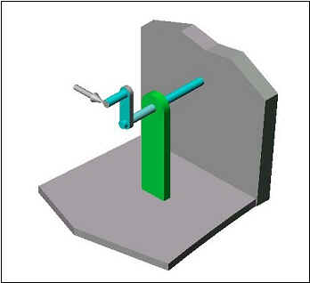
Figure 1
Referring to Figure 1, assume that the handle is attached to the crank-arm so that it is parallel to the supported shaft and is located at a radius of 12 inches from the center of the shaft. In this example, consider the shaft to be fixed to the wall. Let the arrow represent a 100 lb. force, applied in a direction perpendicular to both the handle and the crank-arm, as shown.
Because the shaft is fixed to the wall, the shaft does not turn, but there is a torque of 100 pound-feet (100 pounds times 1 foot) applied to the shaft.
NOTE that IF the crank-arm in the sketch was twice as long (i.e. the handle was located 24" from the center of the shaft), the same 100 pound force applied to the handle would produce 200 lb-ft of torque (100 pounds times 2 feet).
POWER
POWER is the measure of how much WORK can be done in a specified TIME. In the example on the Work and Energy page, the guy pushing the car did 16,500 foot-pounds of WORK. If he did that work in two minutes, he would have produced 8250 foot-pounds per minute of POWER (165 feet x 100 pounds ÷ 2 minutes). If you are unclear about WORK and ENERGY, it would be a benefit to review those concepts HERE.
In the same way that one ton is a large amount of weight (by definition, 2000 pounds), one horsepower is a large amount of power. The definition of one horsepower is 33,000 foot-pounds per minute. The power which the guy produced by pushing his car across the lot (8250 foot-pounds-per-minute) equals ¼ horsepower (8,250 ÷ 33,000).
OK, all that’s fine, but how does pushing a car across a parking lot relate to rotating machinery?
Consider the following change to the handle-and-crank-arm sketch above. The handle is still 12 inches from the center of the shaft, but now, instead of being fixed to the wall, the shaft now goes through the wall, supported by frictionless bearings, and is attached to a generator behind the wall.
Suppose, as illustrated in Figure 2, that a constant force of 100 lbs. is somehow applied to the handle so that the force is always perpendicular to both the handle and the crank-arm as the crank turns. In other words, the "arrow" rotates with the handle and remains in the same position relative to the crank and handle, as shown in the sequence below. (That is called a "tangential force").
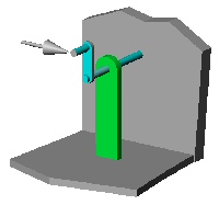
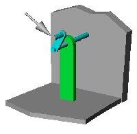
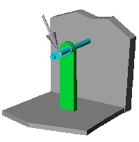
Figure 2
If that constant 100 lb. tangential force applied to the 12" handle (100 lb-ft of torque) causes the shaft to rotate at 2000 RPM, then the power the shaft is transmitting to the generator behind the wall is 38 HP, calculated as follows:
100 lb-ft of torque (100 lb. x 1 foot) times 2000 RPM divided by 5252 is 38 HP.
The following examples illustrate several different values of TORQUE which produce 300 HP.
Example 1: How much TORQUE is required to produce 300 HP at 2700 RPM?
since HP = TORQUE x RPM ÷ 5252
then by rearranging the equation:
TORQUE = HP x 5252 ÷ RPM
Answer: TORQUE = 300 x 5252 ÷ 2700 = 584 lb-ft.
Example 2: How much TORQUE is required to produce 300 HP at 4600 RPM?
Answer: TORQUE = 300 x 5252 ÷ 4600 = 343 lb-ft.
Example 3: How much TORQUE is required to produce 300 HP at 8000 RPM?
Answer: TORQUE = 300 x 5252 ÷ 8000 = 197 lb-ft.
Example 4: How much TORQUE does the 41,000 RPM turbine section of a 300 HP gas turbine engine produce?
Answer: TORQUE = 300 x 5252 ÷ 41,000 = 38.4 lb-ft.
Example 5: The output shaft of the gearbox of the engine in Example 4 above turns at 1591 RPM. How much TORQUE is available on that shaft?
Answer: TORQUE = 300 x 5252 ÷ 1591 = 991 lb-ft.
(ignoring losses in the gearbox, of course).
The point to be taken from those numbers is that a given amount of horsepower can be made from an infinite number of combinations of torque and RPM.
Think of it another way: In cars of equal weight, a 2-liter twin-cam engine that makes 300 HP at 8000 RPM (197 lb-ft) and 400 HP at 10,000 RPM (210 lb-ft) will get you out of a corner just as well as a 5-liter engine that makes 300 HP at 4000 RPM (394 lb-ft) and 400 HP at 5000 RPM (420 lb-ft). In fact, in cars of equal weight, the smaller engine will probably race BETTER because it's much lighter, therefore puts less weight on the front end. AND, in reality, the car with the lighter 2-liter engine will likely weigh less than the big V8-powered car, so will be a better race car for several reasons.
Measuring Power
A dynamometer determines the POWER an engine produces by applying a load to the engine output shaft by means of a water brake, a generator, an eddy-current absorber, or any other controllable device capable of absorbing power. The dynamometer control system causes the absorber to exactly match the amount of TORQUE the engine is producing at that instant, then measures that TORQUE and the RPM of the engine shaft, and from those two measurements, it calculates observed power. Then it applies various factors (air temperature, barometric pressure, relative humidity) in order to correct the observed power to the value it would have been if it had been measured at standard atmospheric conditions, called corrected power.
Recent Change to This Page
At this spot in the page, there used to be an analysis showing how to determine the power consumed by a pump. That discussion has been moved to the more appropriate, recently-updated Engine Lubrication Systems page.
General Observations
In order to design an engine for a particular application, it is helpful to plot out the optimal power curve for that specific application, then from that design information, determine the torque curve which is required to produce the desired power curve. By evaluating the torque requirements against realistic BMEP values you can determine the reasonableness of the target power curve.
Typically, the torque peak will occur at a substantially lower RPM than the power peak. The reason is that, in general, the torque curve does not drop off (%-wise) as rapidly as the RPM is increasing (%-wise). For a race engine, it is often beneficial ( within the boundary conditions of the application ) to operate the engine well beyond the power peak, in order to produce the maximum average power within a required RPM band.
However, for an engine which operates in a relatively narrow RPM band, such as an aircraft engine, it is generally a requirement that the engine produce maximum power at the maximum RPM. That requires the torque peak to be fairly close to the maximum RPM. For an aircraft engine, you typically design the torque curve to peak at the normal cruise setting and stay flat up to maximum RPM. That positioning of the torque curve would allow the engine to produce significantly more power if it could operate at a higher RPM, but the goal is to optimize the performance within the operating range.
An example of that concept is shown Figure 3 below. The three dashed lines represent three different torque curves, each having exactly the same shape and torque values, but with the peak torque values located at different RPM values. The solid lines show the power produced by the torque curves of the same color.
Figure 3
Note that, with a torque peak of 587 lb-ft at 3000 RPM, the pink power line peaks at about 375 HP between 3500 and 3750 RPM. With the same torque curve moved to the right by 1500 RPM (black, 587 lb-ft torque peak at 4500 RPM), the peak power jumps to about 535 HP at 5000 RPM. Again, moving the same torque curve to the right another 1500 RPM (blue, 587 lb-ft torque peak at 6000 RPM) causes the power to peak at about 696 HP at 6500 RPM
Using the black curves as an example, note that the engine produces 500 HP at both 4500 and 5400 RPM, which means the engine can do the same amount of work per unit time (power) at 4500 as it can at 5400. HOWEVER, it will burn less fuel to produce 450 HP at 4500 RPM than at 5400 RPM, because the parasitic power losses (power consumed to turn the crankshaft, reciprocating components, valvetrain) increases as the square of the crankshaft speed.
The RPM band within which the engine produces its peak torque is limited. You can tailor an engine to have a high peak torque with a very narrow band, or a lower peak torque value over a wider band. Those characteristics are usually dictated by the parameters of the application for which the engine is intended.
An example of that is shown in Figure 4 below. It is the same as the graph in Figure 3 (above), EXCEPT, the blue torque curve has been altered (as shown by the green line) so that it doesn't drop off as quickly. Note how that causes the green power line to increase well beyond the torque peak. That sort of a change to the torque curve can be achieved by altering various key components, including (but not limited to) cam lobe profiles, cam lobe separation, intake and/or exhaust runner length, intake and/or exhaust runner cross section. Alterations intended to broaden the torque peak will inevitable reduce the peak torque value, but the desirability of a given change is determined by the application.
Figure 4
Derivation of the Power Equation
(for anyone interested)
This part might not be of interest to most readers, but several people have asked:
"OK, if HP = RPM x TORQUE ÷ 5252, then where does the 5252 come from?"
Here is the answer.
By definition, POWER = FORCE x DISTANCE ÷ TIME (as explained above under the POWER heading)
Using the example in Figure 2 above, where a constant tangential force of 100 pounds was applied to the 12" handle rotating at 2000 RPM, we know the force involved, so to calculate power, we need the distance the handle travels per unit time, expressed as:
Power = 100 pounds x distance per minute
OK, how far does the crank handle move in one minute? First, determine the distance it moves in one revolution:
DISTANCE per revolution = 2 x π x radius
DISTANCE per revolution. = 2 x 3.1416 x 1 ft = 6.283 ft.
Now we know how far the crank moves in one revolution. How far does the crank move in one minute?
DISTANCE per min. = 6.283 ft .per rev. x 2000 rev. per min. = 12,566 feet per minute
Now we know enough to calculate the power, defined as:
POWER = FORCE x DISTANCE ÷ TIME
so
Power = 100 lb x 12,566 ft. per minute = 1,256,600 ft-lb per minute
Swell, but how about HORSEPOWER? Remember that one HORSEPOWER is defined as 33000 foot-pounds of work per minute. Therefore HP = POWER (ft-lb per min) ÷ 33,000. We have already calculated that the power being applied to the crank-wheel above is 1,256,600 ft-lb per minute.
How many HP is that?
HP = (1,256,600 ÷ 33,000) = 38.1 HP.
Now we combine some stuff we already know to produce the magic 5252. We already know that:
TORQUE = FORCE x RADIUS.
If we divide both sides of that equation by RADIUS, we get:
(a) FORCE = TORQUE ÷ RADIUS
Now, if DISTANCE per revolution = RADIUS x 2 x π, then
(b) DISTANCE per minute = RADIUS x 2 x π x RPM
We already know
(c) POWER = FORCE x DISTANCE per minute
So if we plug the equivalent for FORCE from equation (a) and distance per minute from equation (b) into equation (c), we get:
POWER = (TORQUE ÷ RADIUS) x (RPM x RADIUS x 2 x π)
Dividing both sides by 33,000 to find HP,
HP = TORQUE ÷ RADIUS x RPM x RADIUS x 2 x π ÷ 33,000
By reducing, we get
HP = TORQUE x RPM x 6.28 ÷ 33,000
Since
33,000 ÷ 6.2832 = 5252
Therefore
HP = TORQUE x RPM ÷ 5252
Note that at 5252 RPM, torque and HP are equal. At any RPM below 5252, the value of torque is greater than the value of HP; Above 5252 RPM, the value of torque is less than the value of HP.
