Part 2: Block and Cylinder Liners
Design Details
NOTE: All our Products, Designs, and Services are SUSTAINABLE, ORGANIC, GLUTEN-FREE, CONTAIN NO GMO's, and will not upset anyone's precious FEELINGS or delicate SENSIBILITIES.
NOTE: EPI no longer has any involvement in this engine project. Project delays have occurred for a variety of reasons, resulting in conflict between EPI and the client. As a result, the Client-Contractor relationship has been severed by mutual agreement.
I am leaving these pages on the EPI website to describe the engine design details and technology for the general interest of our many readers.
This second part of the series provides design detail about the components that comprise the engine base, and the thought processes that went into the design and execution of those components.
As described in Part 1, I decided on a pushrod cam-in-block arrangement in order provide a compact, lightweight configuration that takes advantage of contemporary engineering and methodology to generate excellent performance (15 bar BMEP naturally aspirated) coupled with the sort of superior reliability that is required for an aircraft powerplant.
ENGINE LAYOUT
My initial concept of the engine was to design a 60° block with the 4.400 in bore spacing common to the old Small Block Chevrolet (SBC) V8 and to the current LS family of engines, and to use a custom six-cylinder version of an existing LS3 or LS7 head design.
My early thoughts were to use a 4.125 x 4.050 inches bore / stroke to produce just under the regulation 650 in³ of displacement. However, a bore of 4.125 inches with a 4.400 inch bore spacing results in a minimum wall between cylinders of only 0.275 in, and would require siamesing the bores to achieve maximum strength and stiffness. That puts unwanted limitations on optimal heat rejection and thermal homogeneity.
Further, with the cast-in-place dry liner arrangement used in the LS engines, or an aluminium block with a shrunk or pressed-in liner as used in other engines, there is the problem of stress distribution that occurs with any composite structure that uses dissimilar materials. Unless the relative stiffnesses of the structural components are balanced relative to the ratio of elastic moduli, the material with the higher modulus will carry a larger proportion of the applied stress.
In the case of ductile iron liners and an aluminum block, the modulus difference is about 2.4 to 1, so the aluminum wall would need to be roughly 2.4 times thicker than the iron liner wall in order to balance the stresses.
If, for example, a designer decided that a ductile iron liner thickness of 0.125 in was sufficient, then the back-up aluminum wall would need to be about 0.300 in thick to balance the hoop stresses, for a total wall of 0.425 in, which would allow a maximum bore of only 3.975 in. It is likely that a ductile iron liner can manage a greater cyclic stress level than cast aluminum, but that potential imbalance problem must be considered.
In addition to my cylinder wall strength concerns, my FEA stress analysis of the initial crankshaft design showed that a thicker web between the rod and main journals would be desirable to support adequately the applied bending and torsional loads.
Crankshaft stiffness and cylinder liner strength requirements, plus coolant flow considerations, led me to alter the layout increase the bore spacing to 4.500 inches, and design a block assembly that comprised an upper and lower component, split at the crankshaft centerline, with wet cylinder liners, and bore-stroke dimensions of 4.065 x 4.160 in, resulting in a displacement of 647.9 in³. Although the smaller bore size limited my intake valve size a bit, it did not impose a meaningful penalty on the breathing characteristics (discussed later in the head design section).
Because of the peak cylinder pressures planned for the full race version, and because of the need to remove quite a bit of aluminum in the bearing bulkhead area to make room for the liners to extend into the block sufficiently, and to provide a sufficient amount of inter-bay breathing area, I chose to use a full bottom-end saddle, which is also made from high-strength aluminum billet. The split line between the upper and lower block (saddle) is at the crankshaft centerline.
Sealing between the upper and lower halves, and in fact throughout the entire engine (with the exception of the bespoke MLS head gaskets), is by means of O-rings that are captured in dovetail-cross-section grooves, which retain the rings in place once they have been installed.
The CAD model of this upper-lower block assembly, with the lifter bushings installed, is shown in Figure 1.
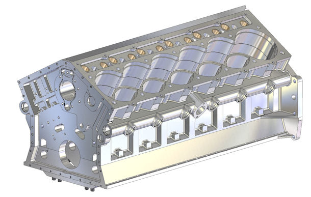
Figure 1: CAD model of the Block Assembly
UPPER BLOCK
The upper block begins life as a 950 lb brick of 6061 aluminium, installed into a precision five-axis CNC milling center. There is no need to use a more exotic or expensive alloy because in these components, the stiffness dictates the section thickness, and the required stiffness provides sufficient sectional area to reduce the stresses to levels suitable for 6061 in the proper hardness.
One of those bricks is shown in Figure 2, just installed into the massive 5-axis milling machine that will turn it into a finished upper block.
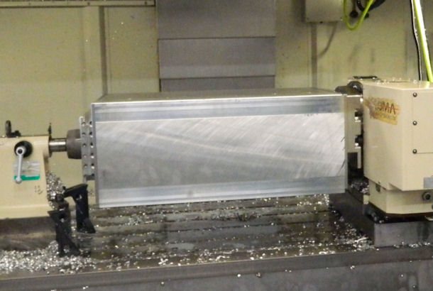
Figure 2: 950 Pound Aluminim Brick
There are four distinct rough-machining set-ups in the 5-axis CNC machining center, during which most of the material is removed. After rough machining is completed, the blocks go out for a proprietary heat treatment process to relieve the stresses and distortions generated by the large amount of material removed. After they return from heat-treating, they go through four more set-ups in the 5-axis mill in which all the finish cuts are done. The end product emerges as a precision, 113 lb. finished upper block, shown in Figure 3.
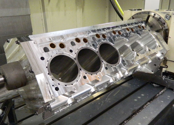
Figure 3: Finished Upper Block with Lifter Bushings and Liners
THIS VIDEO shows just a few of the numerous CNC operations required to produce this masterpiece.
As can be seen in Figure 3, there are seven fasteners around each cylinder. The four primary cylinder head fasteners are 1/2 inch diameter high-strength ARP studs, and the three secondary fasteners are 3/8 inch diameter ARP studs.
The threads for the primary studs begin 3 inches below the deck surface, close to the main bearing bulkheads, as shown in the CAD section drawing in Figure 4. Every thread in the block is formed by rolling rather than being cut with a tap (including the threads that receive helicoils).
The section view in Figure 4 also shows the several fluid galleries (highlighted in blue) that extend through the full length of the block. Those are (a) the main oil gallery below the camshaft tunnel, (b) the two secondary oil galleries above the camshaft tunnel, (c) the two tertiary oil galleries below the cylinder bores, and (d) the two large coolant galleries that extend along the outside of the block next to the liner bores. The details of the functions of those galleries will be described in the sections on Lubrication and Cooling.
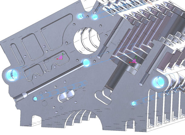
Figure 4: CAD Section of Upper Block
Figure 4 also shows the ample cross-bay breathing passages incorporated into the upper block.
Each lifter bore has an aluminum-bronze bushing shrunk into place, then machined to match the contour of the cam tunnel, and then honed to the finished ID size.
The block deck height is 10.000 inches (254 mm), which was the result of the following: (a) the 4.160 inch (105.66 mm) stroke, (b) the availability of a suitable, high-quality off-the-shelf conrod in a length sufficient for the 1.6:1 rod-to-stroke ratio (6.635 inches / 168.53 mm) I was seeking, and (c) a piston design that allowed a short compression height (1.285 inches / 32.64 mm) without compromising the ring package, yet provided a long enough skirt to assure stability in the bore.
From the perspective of desirable valvetrain stiffness, locating the cam tunnel as far above the crankshaft centerline as is practical is a design goal. Because of the narrow, 60° block vee angle, the cam tunnel in this block naturally fell into a high location, arriving at 7.600 in above the crankshaft axis, which allowed for very short (therefore stiff) pushrods (about 6.50 in center to center).
Another small issue with the narrow block angle is the fact that there are no natural ‘openings’ in the bottom of the cam tunnel, so the installation of camshaft bearings becomes more challenging. I did not want to press the cam bearings all the way across the tunnel until they were at the location in which they would live.
I solved the problem with machined ID reliefs in the tunnel between the bearing locations and by using stepped-OD / constant ID camshaft bearings, with the smallest OD bearing located in the center.
That allows each bearing to be positioned in contact with the edge of its bore, then pressed the remaining short distance into place. The client had no problem machining such a long, complex bore to the tight tolerances required, shown below in Figure 5.
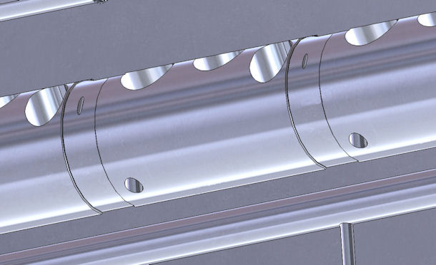
Figure 5: Block Section Showing Cam Tunnel
LOWER BLOCK
The lower block component (also sometimes called a "saddle") incorporates all seven main bearing "caps" into a single, full-length, full-width structural component, also CNC-machined from heat-treated 6061 alloy. The lower block has has a rail on both longitudinal surfaces that projects upward and mates tightly into matching slots in the bottom surface of the upper block.
Four 1/2 inch diameter high-strength ARP studs (total of 28) secure each main bearing bulkhead of the lower block. There are steel sleeve-dowels on each of the inner 1/2 inch studs. Adding to the structure are twenty six 3/8 inch ARP studs around the periphery of the upper / lower split plane, blending the upper and lower block components into a single massively stiff structure. The combination of the dowels and the rails provides a precision locating system for the two pieces, assuring that they mate and re-mate perfectly during reassembly operations.
The saddle tapers outward from the block interface in order to promote better scavenging of the whirling windage mass away from the rotating bits. That tapered profile, plus the O-ring grooves and the indexing rails, can be seen in Figure 6, a section through the CAD model of the lower block. That section also shows additional cross-bay breathing ports in the lower block.
The saddle also provides the mounting pads for the oil pump assembly on one side and for the two tandem coolant pumps on the other side.
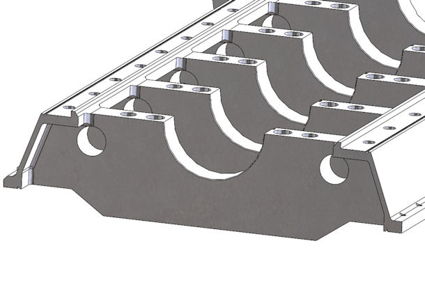
Figure 6: Section Through Lower Block
After the upper and lower block components have been finish-machined individually, they are assembled together using all the dowels and fasteners, torqued to spec, and the main bearing bores and camshaft bearing bores are precision align-bored and honed, forming a matched set of upper and lower block components. Figure 7 shows a nearly-completed lower block.
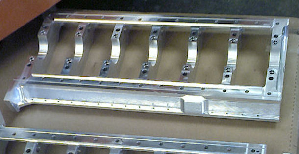
Figure 7: Lower Block CNC'd from Billet Aluminum
The precision that results from those manufacturing operations is demonstrated by the fact that when the crankshaft ( 27-1/4 inches between the centers of the front and rear main bearings), all 14 main bearing shells, the crankshaft thrust bearings, and the lower block are assembled and torqued to spec, then the crankshaft can be spun with one finger and minimal amount of effort (7 lb-in), with only 2.2 thousandths of main bearing clearance. That freedom of rotation is shown in a VIDEO in Part 3.
CYLINDER LINERS
The initial plan for the cylinder liners was to use a customized version of one of the high-quality ductile iron liners on the market. I worked with the chosen supplier to arrive at a mutually approved drawing and specifications, and then placed an order.
When the sample liners were delivered, however, we discovered that the previously agreed (and drawing-specified) tolerances on the critical dimensions had not been met, and the variances were more than what we thought were workable. The company graciously offered to take back the liners and not charge us for them.
At that point, we decided to make the liners in-house, using a hardened medium-carbon, manganese-chrome-molybdenum steel alloy that had been used successfully for liners in aero engines during WWII. Total Seal provided the piston rings, which are specially formulated to seal and wear very well on a high-hardness, steel liner.
The liner wall thickness varies in order to provide good stiffness and distribute evenly the stresses resulting from the high combustion loads anticipated in both the supercharged and turbocharged versions.
The liner is 6-3/8 inches in length. The upper 3-3/4 inches of the liner interface directly to the coolant, and have features on the outside surface to trip the coolant boundary layer and generate greater heat transfer around the hottest portion of the liner. The upper end of the liner is supported by a tight-fitting annulus in the block and by the massive clamping forces at the cylinder head interface.
The lower 2-5/8 inches of the liner is supported by a snug fit into a round bore in the upper block, and it seats against a robust ledge in the upper block. It extends into the crankcase area to provide excellent piston support at the bottom of the stroke, and has cutouts on each side slightly larger than the radius of the crankshaft counterweights.
The coolant is sealed on the lower surface by means of four O-rings at the bottom of the liner, and at the top, by a ridge which mates with the ‘stopper’ ring in the bespoke Cometic MLS head gasket. The external surfaces of the liner exposed to coolant are coated with a phosphate compound that prevents corrosion but does not significantly reduce heat transfer. Figure 8 shows a finished steel liner.
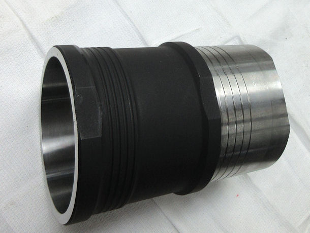
Figure 8: Finished, Coated Steel Liner
