Part 3: Crankshaft
Design Details
NOTE: All our Products, Designs, and Services are SUSTAINABLE, ORGANIC, GLUTEN-FREE, CONTAIN NO GMO's, and will not upset anyone's precious FEELINGS or delicate SENSIBILITIES.
NOTE: EPI no longer has any involvement in this engine project. Project delays have occurred for a variety of reasons, resulting in conflict between EPI and the client. As a result, the Client-Contractor relationship has been severed by mutual agreement.
I am leaving these pages on the EPI website to describe the engine design details and technology for the general interest of our many readers.
CRANKSHAFT LAYOUT
The design of the crankshaft began with some insight provided by a brilliant two-part article by Daniel Whitney that appeared in the 2004 summer and fall issues (Volume 3, Numbers 3 and 4) of Torque Meter, The Journal of the Aircraft Engine Historical Society).
Early on in the article Mr. Whitney points out that, mathematically, 12 independent cylinders can be arranged to fire in almost 20,000,000 different ways, but by adding a requirement that firing events must alternate between banks, the number of possibilities falls to a bit over 580,000. Applying further constraints, such as what he calls a “realistically configured” crankshaft, the number of unique, practical V12 firing orders goes down to nine (using a normalized cylinder numbering scheme).
After studying his analysis, I decided to use a firing sequence based on the following factors. First, I wanted one that worked with a crankshaft having pairs of journals centered on planes separated by 120° (no revelation there, the standard Inline-6 layout). Second, I wanted journal pairs 3-4, 2-5, and 1-6 each in one of those planes (again, standard Inline-6 layout). Third, I wanted the two cylinders on each crank journal firing sequentially, to minimise the cyclic rate of torsional stresses. Fourth, I wanted a firing order in which no two cylinders with adjacent inlet tubes in the plenum could fire in sequence (to reduce inlet interference and crosstalk).
There was also a requirement for the crankshaft to spin in the counter-clockwise direction, as viewed from the accessory drive end. That is because the use of a single mesh gearbox causes the propeller to rotate in the opposite direction to the crankshaft, and propellers in most aircraft of US or Canadian origin rotate clockwise as viewed from the pilot’s seat. Lots of pilots don't adjust well to unfamiliar operational characteristics such as having the propeller rotate in the “wrong” direction.
There are two meaningful benefits to having the engine and propeller rotate in opposite directions. Those benefits accrue from cancelling a portion of the propeller mass moments of inertia (MMOI) with that of the engine.
The propeller has a very large mass moment of inertia (MMOI), and when the aircraft to which is it attached carries out a maneuver that causes the aircraft to rotate about either its pitch or its yaw axis, the spinning propeller generates a gyroscopic moment that acts at 90° to the resultant axis about which the aircraft is rotating.
For example, with a clockwise-rotating propeller (as viewed from the pilot’s seat), if the pilot pushes the stick forward to pitch the nose down, the propeller will generate a gyroscopic moment that tries to turn the aircraft to the right about its yaw axis.
The intensity of that gyroscopic moment varies with the MMOI and RPM of the propeller, as well as the angular rate of the aircraft about its pitch or yaw axis, and requires rudder input by the pilot to maintain coordinated flight.
The benefits come from the fact that the gyroscopic moment of the counter-rotating engine will partially offset (but typically not cancel) the gyroscopic moment generated by the propeller. That net reduction in gyroscopic moment makes the airplane easier to fly by a lower-skilled pilot, and allows the engine mounting structure to be lighter because it does not have to cope with the larger loads imposed by the combined gyroscopic moment of the engine and propeller.
Those parameters determined the crankshaft layout. From there, I went through an extended iterative design process, using the results of detailed FEA studies to arrive at a product that had the cyclic stress levels, stiffness and resonant frequencies I was seeking. Figure 1 shows a CAD model rendering of the fully-counterweighted crankshaft, with the conrod oiling holes drilled properly for counterclockwise rotation. The finished crankshafts, to this design, weigh 75.5 pounds, which is less than a typical Big Block Chevy V8 crankshaft.
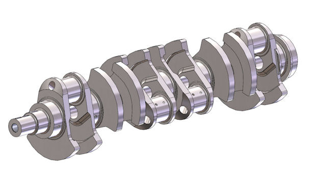
Figure 1: 3D-CAD Model of Crankshaft
CRANKSHAFT LOADS
Initial engine performance simulations suggested that peak cylinder pressures in the 145 bar vicinity would be necessary to produce the desired 1850 hp. Peak cylinder pressures tend to occur at around 10 to15 crankshaft degrees past TDC in a naturally aspirated engine, and 25-30º after TDC in a boosted engine. In either case, the angle between the cylinder axis and the conrod axis is relatively small, so the bending forces imposed on the crankshaft and the resulting restraining forces required in the engine structure can become extremely high.
As an example, a peak pressure of 2100 psi (145 bar) applied to a piston of 4.065 in diameter will exert 27,254 pounds of force on the piston and wristpin. If the rod-to-stroke ratio is 1.6:1, and the peak pressure occurs at 25° after TDC, that force resolves to 27,015 pounds applied to the crankshaft journal and 3,610 pounds applied to the piston skirt-cylinder interface. Fortunately, at 6000 RPM in the vicinity of TDC, the crankshaft applies a substantial acceleration to the reciprocating parts which opposes the combustion loads, thereby reducing the vertical and horizontal loads to about 23,000 and 3,150 pounds respectively.
The crankshaft is a seven main-bearing design which is fully counterweighted on both sides of each of the six rod journals, and all journal fillets are 3.5 mm. The main and rod journals are 3.145 and 2.200 in diameter respectively, providing a substantial crankpin overlap value of 0.592 in. That overlap, plus the generous cheek widths and the large journal diameters, provide a large contribution to the massive torsional and bending strength of this crankshaft.
The weight-reducing bores in the rod journals are off-centre from the journal axis so as to provide a better distribution of material around the oil holes. They are cut in from each end of the journal at an angle (instead of the usual method of parallel to the crank axis) and do not go all the way through the journals. The angled lightening holes were required in order to drill them without cutting material off the counterweights, but they provide an additional advantage of leaving a full support wall in the center of each journal.
The conrod bearing oiling passages are drilled to account for the counter-clockwise rotation, feeding oil into the bearing space during the compression stroke, thereby providing a full oil supply before combustion and uninterrupted hydrodynamic surfaces to bear the combustion loads.
The conrod oiling holes are smaller in diameter to those found in everyday V8 crankshafts. That is (a) to minimize stress concentrations where the holes pass close to other surfaces, and (b) to reduce the size of the hydrodynamic pressure interruption where the drilling intersects the surface of the journal.
The flywheel attachment flange includes a 2.067 inch diameter flywheel centering spigot, and uses eleven 7/16x20 bolts and a single hardened 0.4375 inch dowel for flywheel retention and alignment, assuring problem-free transmission of the substantial engine torque. As mentioned above, the finished weight of the crankshaft is 75.5 lbs.
Working closely with the engineers at Bryant Racing, my 7-page crankshaft definition drawing went through several revisions in order to simplify the machining operations and arrive at the final design. Bryant precision-machines this crankshaft from a billet of a proprietary medium-carbon, chrome-nickel-molybdenum-silicon-vanadium alloy steel made specifically for the company. The finish work consists of several closely controlled in-house processes including proprietary heat treatment, cryogenic processing, ion-nitriding and REM isotropic superfinishing.
Because of the 120° throw separation, one would expect this crankshaft to be in perfect dynamic balance without the need for bobweights. Consistent with the precision that Bryant provided, these crankshafts spin with zero indication of imbalance with no bobweights. As a test, I installed bobweights appropriate for the rotating and reciprocating masses and spun the crank again. And once again, it showed zero imbalance.
Figure 2 shows the first three finished crankshafts.
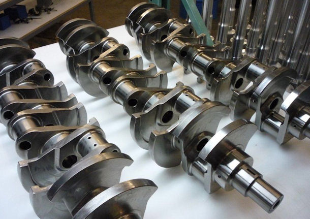
Figure 2: First Three Finished EP-V12 Crankshafts
Figure 3 shows the crankshaft installed in the upper-lower block assembly. With no seals installed, it turns freely with a flick of the wrist, as if it were in needle bearings instead of hydrodynamic bearings, as shown in the video below.
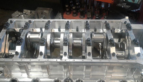
Figure 3: Crankshaft installed in Block
