Part 4: Pistons, Wristpins, and Conrods
Design and Analysis Details
NOTE: All our Products, Designs, and Services are SUSTAINABLE, ORGANIC, GLUTEN-FREE, CONTAIN NO GMO's, and will not upset anyone's precious FEELINGS or delicate SENSIBILITIES.
NOTE: EPI no longer has any involvement in this engine project. Project delays have occurred for a variety of reasons, resulting in conflict between EPI and the client. As a result, the Client-Contractor relationship has been severed by mutual agreement.
I am leaving these pages on the EPI website to describe the engine design details and technology for the general interest of our many readers.
PISTONS
The basic piston design is a box-bridge piston made in 2618 alloy, having two different crown designs, one for the naturally aspirated version, and a different layout for the boosted versions.
I initially sought to have my design manufactured from off-the-shelf forging blanks for the common 4.065 bore size. After working out the stiffness and stress distributions in my design, I contacted a prominent and highly respected piston company to discuss sourcing my pistons.
I submitted my drawings, 3D CAD models and stress analysis results to them. After examining the design, they agreed to manufacture an initial order of 36 pistons. A few weeks later, however, they suddenly reneged on our agreement and declined to produce them, claiming “liability issues”.
Subsequently I made numerous contacts with other piston manufacturers and submitted my solid models and drawings to various companies that advertise box-bridge products. However, I was unable to obtain a suitable box-bridge forged piston.
Finally, United Engine and Machine Company (UEM, producers of Keith Black, Hypereutectic, and other brands) agreed to do my design in billet 2618 for the first three development engines (they did not have any suitable forging blanks). They were extremely helpful and produced high-quality coated pistons for us (Figure 1), with the restriction that I guarantee that they would not be used in a flying engine.
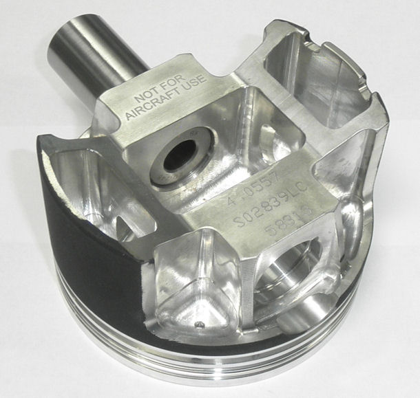
Figure 1: Billet UEM Piston for the Naturally-Asiprated EPI V12
During the development and testing processes, the UEM billet pistons (and any subsequent modifications to the design) will be used in the test engines until we settle on the optimal ovality, taper and skirt stiffness parameters. At that point, we will manufacture the production pistons in-house from bespoke 2618 forging blanks.
The perceived problem of "liability" in aircraft engines is pervasive among aftermarket suppliers. To me, that perception appears to be rather silly when viewed against the backdrop of the multitudes of aftermarket engine parts being used in various forms of automobile racing. The spectacular engine explosions and subsequent crashes that occur in close proximity to spectators in the extreme forms of upper-echelon drag racing, and the astounding crashes that occur at Daytona and Talledega (and now regularly at other tracks as a result of the idiotic 2019 CUP “parade-racing” rules package from the NASCAR braintrust), makes the potential for litigation seem far more probable from those forms of exposure that are deemed ‘acceptable’ than from infrequent experimental aviation endeavours.
That flawed perception of risk has plagued me ever since I have been working on aero engines and continues unabated, providing me with a huge motivation to take my business offshore to source some rather expensive parts. Domestic manufacturers apparently see no issue with driving business away from their marketplace.
My mention of the fact that the originally-contracted piston company supplies pistons for NASCAR, Top Fuel, Funny Cars, other extreme forms of racing, and even to builders of Lycoming race engines, did not seem to trigger a realization of their inconsistency and hypocrisy. Suffice it to say there will NEVER be another piston in my shop from a company whose name starts with “Ma”)
OK, now back to the piston. The weight of the piston for the naturally aspirated version of the engine is 631 g. The supercharged and turbocharged versions have quite different crown and bowl configurations from the NA version, and require a bit more material to achieve the required strength and stiffness. Consequently those weigh 747 g.
Figures. 2 and 3 show some of the results of our FEA of the boosted piston design. These pictures show the analysis for 175 bar of cylinder pressure at a crank angle of 27° ATC. Figure 2 shows that the stresses in the upper portion of the piston are comfortable, with a peak of about 25 ksi (172 MPa) at the intersection of the pin columns and the crown.
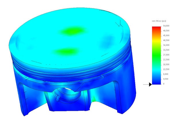
Figure 2: FEA of Crown Area of the EPI Piston, Boosted Version
Figure 3 shows the peak stresses in the underside of the piston to be quite high (50 ksi, 344 MPa) in the area of the inner wristpin contact surfaces. Those high stresses are due in part to the deformation of the wristpin, shown in Figure 3 under the influence of the 175 bar cylinder pressure (nearly 33,000 lb of force). Fortunately, the area of extremely high stress in the wristpin bore will yield in service and deform to better mate with the deformed wristpin shape. The stresses in the wristpin interface area with the naturally aspirated versions are dramatically lower.
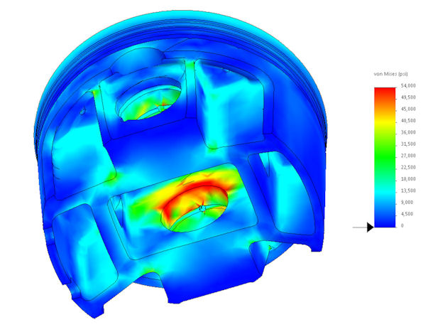
Figure 3: FEA of Pin Area of the EPI Piston, Boosted Version
WRISTPINS
The wristpin outside diameter is 0.990 inch with a length of 2.500 inches. The wall thickness is a constant 0.250 in order to minimise bending and ovality deflections. The material is a high-strength tool steel, hardened to provide extreme wear resistance, and high strength together with high ductility. They have chamfered edges and are retained in the pistons using round wire locks. The weight of the pin is 184 g.
Despite the effort to minimise pin distortion, the stress and deflection studies of these parts under high cylinder pressure (175 bar) show a substantial amount of both elastic bending and ovality, as shown in Figure 4. (The visual deflection multiplier in that figure is 50.)
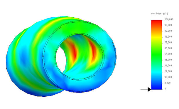
Figure 4: FEA of EPI V12 Wristpin Deflection, Heavily Boosted Version
The level of deflection in the pins and the resulting stresses imposed on the piston have caused me to revisit the specifics of the piston and wristpin components for the highly boosted engine version, with the focus being on a larger diameter, thicker wall wristpin, a lower wristpin bore location in the piston to accommodate that bigger pin, and of course a somewhat shorter rod length.
CONRODS
Our V12 conrods [Figure 5] are a Carrillo billet product, an off-the-shelf Big Block Chevy V8 H-beam production made from an aircraft-quality medium-carbon nickel-chrome-moly-silicon alloy, heat treated to a tensile strength of about 180 ksi with a very high impact strength, and shot peened for improved fatigue resistance. They have bronze-bushed wristpin bores, sleeve dowels for rod-cap alignment, and 7/16 inch diameter MP-35 fasteners. The center-to-center length is 6.635 inches and the weight, with bearings, is 872 g.
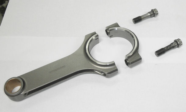
Figure 5: EPI V12 H-Beam Connecting Rod
Some aftermarket H-beam conrods exhibit the disturbing property of having the big-end bore dimensions change after the caps have been removed and re-installed at the proper rod bolt stretch value. I have dial-bore-gauged big-end measurement changes in the big-end inside diameter on some aftermarket products as high as 0.0012 inches diameter and consequently ovality. This particular brand of conrods is of such quality that it is fundamentally free from that problem. The worst change I have seen with these Carrillo rods is a change of 0.0001.
Figures 6 and 7 are FEA plots of the stresses and deflections of the V12 H-beam rod with 175 bar of cylinder pressure applied at both 12° and 27° ATC. The asymmetry of the resultant stress is a product of the column deflections in the Y (hinged) direction.
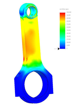
Figure 6: 12 Deg ATC |
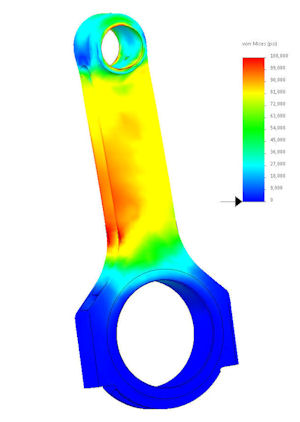
Figure 7: 27 Deg ATC |
FURTHER OBSERVATIONS
It is commonly believed that H-beam rods provide the most strength to resist deformation under high loads. However, a quick study of the conecting rod application shows that a conrod is a hinged column in the plane perpendicular to the crankpin axis and centered on the piston (which, for convenience, I will call the Y direction) and is approximately a fixed column in the plane that is parallel to the crankpin axis and intersects the wristpin axis (the X direction).
The resistance of a column to buckling deflections is proportional to the polar moment of inertia (PMOI) of the cross-section (for a given material and length). The Euler analysis of columns shows that a column with fixed ends is four times more resistant to buckling deflection than one with hinged ends having the same length and PMOI.
Since a column will always tend to buckle in its most limber (hinged) direction, it is interesting to examine the relative stiffness of an H-beam and an I-beam rod of similar proportions.
When one compares the relative values of PMOI for an H-beam rod having the dimensions of our V12 rod against those of an I-beam rod having the same width and thickness (1.375 and 0.625 respectively) as the H-beam, and with similar wall thicknesses, it is interesting to note that for the H-beam, the PMOI is 2.1 times greater in the Y (hinged) direction than in the X direction, but for the I-beam design, the PMOI is 4.5 times greater in the Y (hinged) direction than in the X direction.
Comparing the two types of beam section, the I-beam PMOI is 2.7 times greater in the Y (hinged) direction and 1.2 times greater than the H-beam in the X (fixed) direction. The only place where the H-beam wins is in the cross-sectional area, which is roughly 1.2 times greater than the I-beam rod. So it is important to compare both the compressive stresses and the bending stresses applied to the rod. On the same subject, it is also interesting to note that many of the Formula-1 engines use an optimized I-beam design.
I am currently considering changing over to an optimal I-beam section for the boosted versions of this engine.
