Part 5: Valvetrain
Camshaft, Lifters, Pushrods, Rockers, Valves, Springs
NOTE: All our Products, Designs, and Services are SUSTAINABLE, ORGANIC, GLUTEN-FREE, CONTAIN NO GMO's, and will not upset anyone's precious FEELINGS or delicate SENSIBILITIES.
NOTE: EPI no longer has any involvement in this engine project. Project delays have occurred for a variety of reasons, resulting in conflict between EPI and the client. As a result, the Client-Contractor relationship has been severed by mutual agreement.
I am leaving these pages on the EPI website to describe the engine design details and technology for the general interest of our many readers.
CAMSHAFT
The single carburized 8620 steel camshaft [Fig. 1] is gear-driven and runs in seven pressure-lubricated 2.165 in (55 mm) hydrodynamic bearings. The camshaft is a hollow production with a 0.669 inch center bore and a minimum core diameter of 1.220 inches in order to obtain the required torsional and bending stiffness. Those physical constraints allow for a maximum lobe lift of about 0.453 inches..
The cams are manufactured for us by Comp Cams in accordance with our detailed 5-sheet cam definition drawings. Those drawings required quite a bit of work and cooperation with Comp in order to (a) correctly specify the axial location and angular orientation of each of the 24 lobes (in view of the 30-degree intake lifter axes and the 36 degree exhaust lifter axes), and (b) the fact that the camshaft rotates in the opposite direction to that commonly encountered in the aftermarket camshaft industry.
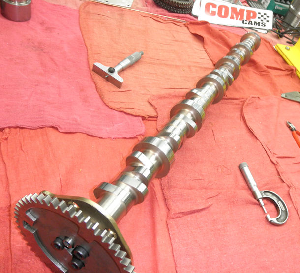
Figure 1: V12 Camshaft, Locator Plate and Drive Gear
The camshaft is located axially by a phosphor-bronze thrust plate that is captured between the drive gear and the front bearing journal. The camshaft drive gear contains the triggering ramps that enable the cam position sensors to determine where in the two-revolution cycle the engine is currently located. It also contains a machined recess that allows me to use the Cloyes Hex-Adjust mechanism for precise adjustment of the cam phasing.
The lobe profiles I selecterd are from the extensive Comp Cams hydraulic-roller profile library. Those asymmetric lobes have very smooth acceleration and velocity curves, (Figure 2) with modest peak positive acceleration rates in order to open and close the valves quickly, together with a long, smooth negative acceleration profile, making it easier for the valvespring to manage slowing the system to a stop and then accelerating it to peak closing velocity (which is to say, maintaining the lifter-to-lobe contact).
These lobes have a soft closing ramp (evident in Figure 2), making them very suitable for aircraft, marine, and industrial applications where high area under the lift curve is desirable while at the same time providing low valve seat erosion over an extended period of operation. The amplitudes of the lobes’ excitation content in the higher harmonics decline quickly as the order increases, which reduces the spectrum of excitation frequencies the springs must cope with.
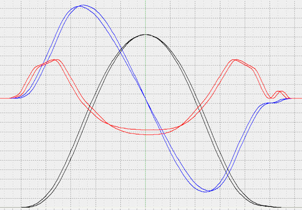
Figure 2: V12 Typical Cam Lobe Lift, Velocity, and Acceleration Profiles
CAM FOLLOWERS
The cam followers (lifters) for the naturally-aspirated and supercharged versions (4800 – 5000 RPM,) are a high-performance version of a Big Block Chevy (BBC) hydraulic roller. The 6000-RPM turbocharged (race) version will use a custom lifter that has hydrodynamic bearings and larger axles to eliminate the extraordinarily high Hertz stresses that occur on the axle surfaces because of the combination of high dynamic loads and the tiny contact area provided by the traditional needles between the roller and the axle.
The axis of the intake lifters is parallel to the cylinder axis (30° from vertical), while the axis of the exhaust lifters is 36° from vertical in order to keep the exhaust rocker arms from being excessively long and excessively angled. The BBC layout (alignment flats perpendicular to the roller axis instead of parallel like the SBC) was necessary in order to allow the 6° separation between the axis of the intake and exhaust followers.
The lifters run in leaded phosphor-bronze bushed bores in the block and use custom tool steel plates to maintain alignment. The alignment plates rest in a machined 0.375 inch deep channel in the top of the block and are captured there by the cylinder head.
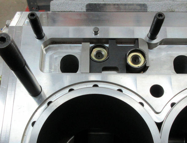
Figure 3: Lifter Alignment Bars in their Channel
The lifter bushings are shrink-fitted to their bores and initially project into the cam tunnel. When the cam tunnel is finish-bored, the bottoms of the lifter bushings are machined flush with the contour of the cam tunnel, providing maximum possible bushing length for lifter support. The upper part of each bushing is flush with the bottom of the alignment plate channel, providing support for the lifter right up to the alignment flats.
PUSHRODS
Because of the high location of the camshaft in the block, the Manton 3/8 OD, 0.065 wall alloy steel pushrods are short, having lengths of 6.475 (164.5 mm) and 6.180 in (157 mm) for the intake and exhaust respectively.
ROCKER ARMS
The alloy steel rocker arms are a bespoke I-beam design that I modified from an existing version of the Jesel J3S rocker. The I-beam design maximizes the stiffness in the major loading direction. The rockers have a nominal ratio of 1.70, pivot on pressure-lubricated needle-bearing trunnions and have tool steel roller tips that run on custom needle bearings. The rockers, shafts, thrust washers and pedestals are produced by Jesel from my drawings [Figure 3].
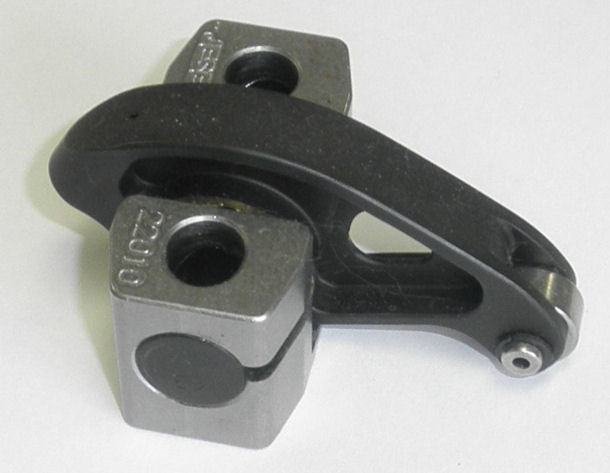
Figure 4: V12 Intake Rocker Arm
The goal in setting rocker-to-valve geometry is to minimize the scuffing component of rocker motion on the valve (ie, minimize dragging of the rocker tip across the valve tip) when the forces are highest, in order to minimize valve guide wear.
There is a common theory on rocker geometry that says that a line from the center of rotation of the rocker to the center of the radius of the rocker tip should be perpendicular to the valve axis at mid lift ("Mid-Lift Geometry").
HOWEVER, if you look more closely at the acceleration curve for any cam lobe (or the V12 lobe shown in Figure 2), it is clear that the positive acceleration peaks (opening and closing) occur well before and after mid lift (respectively). In fact, for my lobes in particular, the acceleration peaks occur at approximately 12% of lift.
At low RPM, the valvespring load is the major component of rocker-to-valve forces. However, at higher rpm, the spring force is mostly consumed by decelerating the valvetrain to a stop (at max lift) and accelerating it back toward closing, keeping the lifter in contact with the cam lobe (ideally). The maximum forces at high RPM occur at the peaks of the acceleration curves, as shown by the green curve in Figure 5.
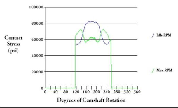
Figure 5: Lifter-to-Lobe Contact Stress vs. RPM
Since it is ovbious that the force between the rocker tip and the falve will be maximum at peak acceleration, then it follows that the perpendicularity constraint shoul occur at or close to peak acceleration, not at mid-lift where the contact forces are rapidly diminishing to the (relatively low) load applied by the valvespring.
The 12% perpendicularity rule is what is applied in this engine.
VALVES
The valves are custom items made by Manley to my drawings, using its NK-844 alloy for the intakes and XH-432 extreme temperature alloy for the exhausts. Both intake and exhaust valve stems are made with the round-groove "bead-lock" retainer lock grooves. The full-radius profile of the grooves provides a substantial reduction in stress concentratioins around the keeper, which is especially important in this high-vibration environment.
VALVE SPRINGS
The valve springs are a high-rate (approximately 440 ponds per inch) conical design from Comp Cams, made from very high purit,y vacuum-arc-remelt, chrome-silicon-nickel-vanadium steel wire having an ovate cross section. The springs go through proprietary heat treatment processes, then are isotropic-superfinished, then are micropeened. Those features combine synergistically to provide a spring with high spring rate and high fatigue life.
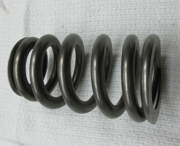
Figure 6: V12 Conical Valvespring
In order to assure the best possible consistency in valvetrain frequencies, I measure and record the rate of every spring in a batch and from that batch, I select a set of springs for one engine so that the rates of all 24 springs for that engine are within ±1.0% of each other.
The performance of the V12 valvetrain will be examined in Spintron testing of several different configurations.
The beauty of conical springs is that each coil has a different resonant frequency, which provides a spring that does not have a fixed resonant frequency. That makes the spring much less susceptible to resonant vibration excited by cam lobe harmonics and from opening and closing impacts, as illustrated by the following graph (courtesy of Comp Cams).
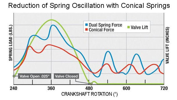
Figure 7: Chart Showing Reduced Oscillation with Conical Springs
For an amazing demonstration of the motion that a valve spring, retainer, and valve stem experiences at high RPM and the resulting valvespring fracture,
check out THIS VIDEO
