Part 6: Cylinder Head
Design and Development
NOTE: All our Products, Designs, and Services are SUSTAINABLE, ORGANIC, GLUTEN-FREE, CONTAIN NO GMO's, and will not upset anyone's precious FEELINGS or delicate SENSIBILITIES.
NOTE: EPI no longer has any involvement in this engine project. Project delays have occurred for a variety of reasons, resulting in conflict between EPI and the client. As a result, the Client-Contractor relationship has been severed by mutual agreement.
I am leaving these pages on the EPI website to describe the engine design details and technology for the general interest of our many readers.
The design, development and production of the cylinder head for this engine consumed a disproportionately large amount of time and effort, and resulted in three iterations of the head design before we got it right (sort of).
My initial cylinder head plan, which was based on the 4.400 cylinder spacing discussed in Part 1, was to convince one of the several manufacturers of good aftermarket LS-7 cylinder heads to add two cylinders onto an existing head casting for me, thereby generating a six-cylinder LS-7-style head which would provide the basis for developing a good, high-flow, fast-burn head for the engine.
I thought the plan was eminently simple and could be easily accomplished. The manufacturer’s existing cylinder head core patterns could be used without change, because the cores are produced as single-cylinder entities and stacked into the drag (lower mold). Likewise, the existing gating, feeds and sprues would be suitable. A new cope and drag would be needed for the six-cylinder version, but the design features could easily be copied from the four-cylinder versions.
Such a cylinder head would have the advantages of (a) using a well-proven design to provide the basis for a head that breathes very well, (b) taking advantage of the inline, in-plane valve layout of the LS-7 and therefore (c) being able to select appropriate components from the copious array of OEM and aftermarket valve gear for the LS engine family, (d) thereby achieving reduced development costs and lower engine prices.
Two sets of circumstances conspired to thwart that plan.
The first was that none of the cylinder head companies I contacted was the least bit interested in doing such a project. The common reason given was that they were “too busy doing high-volume aftermarket production” to engage in a project that had a smaller market potential, regardless of the fact that we were willing to fund the development of the new tooling and pay market price for the castings.
The second circumstance was the design decision to change to a 4.500 inch bore spacing (also discussed in Part 1). Having decided to do a custom cylinder head design, it was an easy next step to decide to emulate the ‘wedge-hemi’ configuration common in Cup engines.
The first iteration (Gen-1) of the 4.500 spacing head looked promising initially.
The second iteration (Gen 2) of the 4.5 inch head design was an attempt to produce a version of the Gen-1 head that could be CNC-machined from billet in order to avoid the tooling costs involved in low-volume casting processes. That design had an upper and lower half in order that the required coolant passages could be CNC-machined, and the halves were doweled and sealed together with O-rings, secured by the clamping force of the head attachment studs.
I had a rapid prototype (RP) of a single-cylinder version of this head produced and did some initial flow development on it. Because of some less-than-optimal layout decisions I made, the head did not show signs of being able to flow as much as I wanted. Further, during the evaluation process, I became concerned that the two-piece design would fall victim to destructive fretting at the boundary junctions.
The FEA results on that design, done with the anticipated high peak cylinder pressures and the very high but very localised stud clamping loads, showed relative motion deflections at the upper and lower half boundary interfaces. That motion between the halves thoroughly supported my anxiety about the fretting issue. There was also a problem in sealing the upper and lower parts of the exhaust port successfully. Those issues caused me to scrap that effort.
The Gen 3 version incorporated some basic layout changes, better port location and aiming, and a better combustion chamber layout. That one looked like a winner, in terms of intake and exhaust flow curves, structural stiffness and coolant flow properties.
The head design evolved with an intake valve axis (relative to a longitudinal plane perpendicular to the deck) of 11° (valve angle), and relative to a transverse plane perpendicular to the deck it is 4° (valve cant). The exhaust valve has angle and cant values of 8° and 4° respectively. The intake port has a cross-sectional choke area of 2.45 in² for the purpose of maintaining high port velocity, and the intake and exhaust valve head diameters are 2.160 and 1.550 inches respectively.
I purchased a single-cylinder rapid prototype (RP) of that Gen 3 design and began the flow development process [Figure 1]. The successful achievement of my flow targets did not come easily. Admittedly, those targets were somewhat ambitious, given the inherent limitations of the bore diameter, valve head maximum diameters and my relatively small intake port choke area.
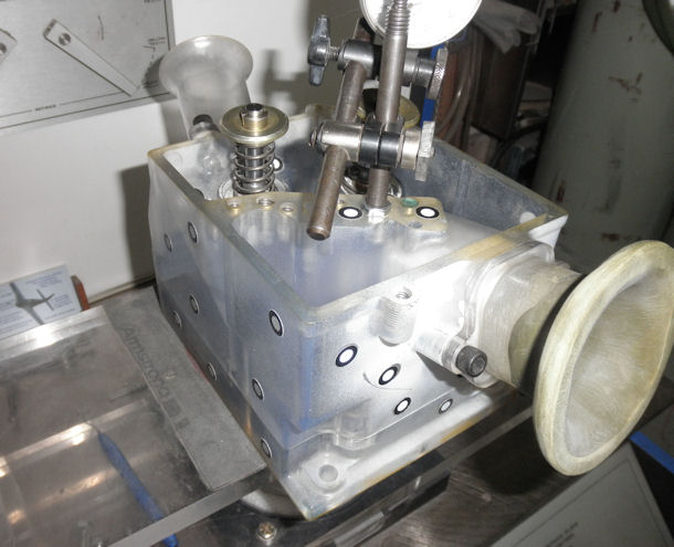
Figure 1: Gen-3 Rapid Prototype Flow Development
During that development effort, it became painfully evident that I did not have quite the level of skills in flow optimisation that I initially thought. The ports were beautifully shaped, contoured and angled, and produced very nice low and mid-lift flows. However, I was unable to get the high-lift intake flow above 352 cfm (0.600 inches lift and 28 inches H2O delta-P).
Eventually, I turned the port development over to an “expert” from NASCAR-land. He re-contoured the ports without enlarging them, while keeping the exterior intake port entrance and exhaust port exit locations in the same places. He also moved both valves from where I had them located.
The high-lift results were somewhat gratifying. At 28 in. H2O delta-P and 0.600 lift, the intake flow is 386 cfm and the exhaust flow is 266 cfm. However, those gains were made at the expense the low and mid-lift flow numbers that the RP had when I sent it to him. I had specifically stated that I did not want to lose the low and mid-lift (0 to 0.400 lift) flow numbers.
But that wasn't the MAJOR problem.
Unfortunately, I did not discover the MAJOR disaster until I began building the first prototype engine. To my immense chagrin, when I installed the custom (EXPENSIVE) Cometic MLS head gaskets onto the heads, with the locating dowels in place, I discovered that the steel gasket substantially intruded into the combustion chamber in the areas of the intake and exhaust valves.
My “head expert”, in the apparently mindless pursuit of bigger high-lift numbers, had recontoured the combustion chamber so that the outer edges were far beyond the edges of the liners, DESPITE the fact that when I sent him the RP head for development, I also sent along my 4.060 bore flowbench adapter so that there was no question about where the cylinder and sealing edges are located.
The existing heads reach their respective flow plateaus at 0.750 lift, with 398 and 277 cfm flows respectively. Furthermore, the flow curves do not reverse at higher lift values.
Figure 2 shows the intake and exhaust port flows. (Too bad they can’t be used on the engine in its current 4.065 inch bore size configuration.)
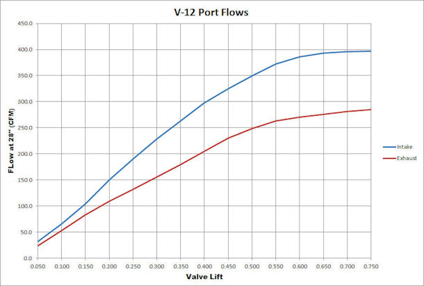
Figure 2: Port Flow Curves at 28" H2O
When my "developed" RP came back from the “expert”, and before I discovered the disaster, we had the ports and combustion chamber laser-scanned to produce 3D models, and I inserted them into the existing head CAD model.
From that final model, Sycast produced the magnificent A-356-T6 heat-treated castings, using monolithic printed core technology and conventional cope and drag components. One of the several improvements that Sycast made was the placement of critically-located chills in the molds to insure the integrity and hardness of the cast metal around the combustion chamber and the head deck. Figures 3 and 4 show the first castings.
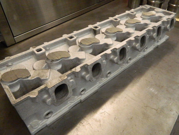
Figure 3: First Casting of the V12 Head - Top and Intake View
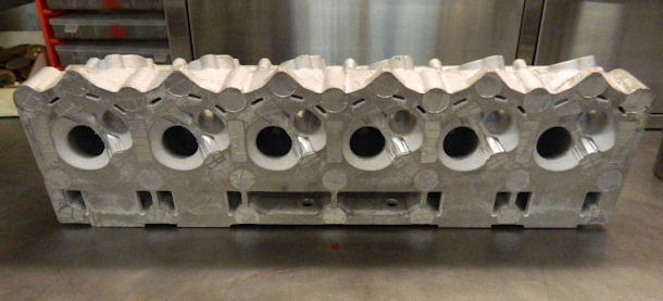
Figure 4: First Casting of the V12 Head - Combustion Chamber View
The monolithic core casting technique has several advantages, not least of which is the elimination of the need to provide draft in the various surfaces (needed with conventional core boxes so that the cores can be extracted from the molds). Another very nice advantage is the fact that with the monolithic core, there is no casting flash between the cylinders, eliminating a major source of essentially randomised disruption to homogeneous coolant flow.
In retrospect, I should have caught the chamber-to-bore mismatch problem when the modified RP came back, before having it laser-scanned and before incorporating its ports and combustion chamber into the CAD model. But since I had provided "the expert" with my 4.060 bore adapter, I never thought to check the resulting combustion chamber against the gasket.
So now, in order to get a head gasket to seal using these heads, and not protrude into the combustion chamber, I have to (a) re-bore and re-hone the liners to achieve a cylinder bore of at least 4.160, (b) scrap the 4.065 pistons and rings, (c) get new pistons and rings to match the new bore size, and (d) get new tooling made at Cometic and some revised MLS gaskets.
For readers wondering about intake port volume, I have no idea what it is, nor do I have any interest in that popular yet completely meaningless metric. I can make two ports having identical port volumes that produce wildly different flow numbers. Port taper rate, the value and location of minimum port cross-sectional area (choke), and bowl configuration are initial values of interest in port design.
COMBUSTION CHAMBER
Our V12 combustion chamber is an open, single spark plug design focused on excellent flow and combustion properties. It has a relatively small volume, is very active in mixture motion and squish, and the spark plug is located fairly close to the geometric center. The perceived single-plug ignition reliability issue is covered by having a separate ECU for each bank of cylinders, each with ‘limp-home’ modes of operation to cope with the failure of critical sensors (discussed in Part 7).
Figure 5 shows a finished combustion chamber, before the ports were machined.
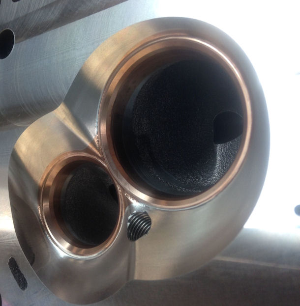
Figure 5: Combustion Chamber (Before Ports are Machined)
I decided against using a two-plug-per-cylinder configuration for several reasons. The first was simply the constraints of the optimised port and chamber geometry.
With regard to the perceived "dual-plug reliability" on aero engines, that dual-plug configuration in conventional piston aero engines is an artifact from the early days of aero engine development (nearly a century ago) in which the magnetos used for ignition were notoriously unreliable.
A large percentage of contemporary aero engines still use dual farm-tractor magnetos (which are still somewhat "reliability-challenged").
The better reason for dual plugs per cylinder is the potential for improvement in the consistency of ignition and in the speed of combustion.
Flame front propagation in a large diameter cylinder can be problematic, even if the spark plug is centrally located. That problem (along with a few others) is significantly reduced by the use of two spark plugs per cylinder, located at opposite edges of the combustion chamber.
Traditional aero engines are limited to relatively low RPM (typically 2600-3000) by virtue of the previously discussed performance properties of air propellers. Therefore, they rely on large displacement for the production of the required power levels.
Those large displacement cylinders come with generous bore diameters. For example, the Pratt & Whitney R-1340, R-2000, R-2800, and R-4360 engines had bore diameters of 5.750 in; the Allison V-1710 was 5.500; the Rolls-Royce Merlin was 5.400 in.
That trend continues in contemporary aero engines. The Lycoming IO-360 / 540 / 720 engines are 5.125 in. and the Continental IO-520 / 550 engines are 5.250 in.
The flame front propagation problem is dramatically demonstrated by the results of te standard pre-flight ignition test. During that run-up test at 1500 RPM, a typical Lycoming 360 / 540 / 720 engine is expected to lose about 100 RPM when either one of the two ignition systems is briefly shut off. The original RPM is restored when the off-system is turned back on. That shows the effectiveness of the dual ignition with plugs at opposite edges of the chamber.
On the other hand, I have built Small Block Chevrolet "aircraft" engines using a side-by-side two-plug design that showed no measurable difference in performance with both systems active or with either one shut off.
Side-by-side plugs increase ignition probability by a calculable-but-apparently-immeasurable amount, but do provide the perception of "aircraft reliability".
COMBUSTION ANALYSIS
In addition to the basic head design, I provided material in the head so that sensors to measure the instantaneous pressures from the combustion chambers and the intake and exhaust ports (just above the valves) can be installed on developmental engines. That will allow a full combustion analysis program to occur after the initial development work is complete on the naturally aspirated version of the engine.
We plan to do a comprehensive combustion analysis at one of the prominent NASCAR engine facilities and make whatever changes are needed to optimise the engine flatline characteristics.
