- 7: Intake and Fuel Systems -
Manifolding and Fuel Delivery
NOTE: All our Products, Designs, and Services are SUSTAINABLE, ORGANIC, GLUTEN-FREE, CONTAIN NO GMO's, and will not upset anyone's precious FEELINGS or delicate SENSIBILITIES.
NOTE: EPI no longer has any involvement in this engine project. Project delays have occurred for a variety of reasons, resulting in conflict between EPI and the client. As a result, the Client-Contractor relationship has been severed by mutual agreement.
I am leaving these pages on the EPI website to describe the engine design details and technology for the general interest of our many readers.
One of the major constraints on the intake system for this engine was that it had to be able to fit within the cowling of the aircraft for which it was originally designed, a carbon fiber 75% scale replica of the famous P-51 WW2 fighter. The cowling has a limited vertical space between the propeller axis and its top profile, and the width of the cowling diminishes rapidly in the forward areas where it blends with the spinner. This constraint is shown below in Figure 1.
.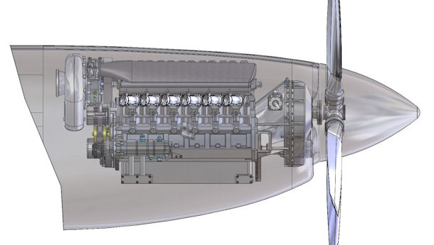
Figure 1: Side View of Engine Tight Fit into Cowling
The naturally aspirated and supercharged intake system consists of a pair of mirror-image plenums (plenae ?) and twelve identical-length, identical-shape runners. Each plenum has its own throttle body and MAF sensor, and there is a balance tube running between the plenums. The plenums and runners are constructed from carbon fiber-epoxy composite.
Figure 2 shows a CAD rendering of the long-runner intake system and two intake plenums, with the injector nozzles installed, but without the fuel rails. I designed the long-runner version to help focus the torque peak close to 4000 RPM.
The plenum has a diffuser section just behind the throttle body to slow the incoming air and recover some of the pressure. The centerline runner length from the plenum to the back of the intake valve is about 17.4 inches. The runners and plenums are carbon-fiber-reinforced epoxy.
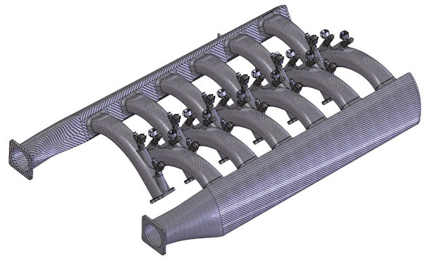
Figure 2: Intake Manifolding System
The runners have a slight taper from the plenum to the cylinder head, where they match the relatively small cross-sectional area of the intake ports. The higher-RPM turbocharged race version uses a single, larger throttle body and a centrally located plenum, with considerably shorter and more tapered runners.
Each runner contains bosses to accommodate two Injector Dynamics fuel injector nozzles.
In the naturally aspirated version, a single set of Injector Dynamics precision injectors will satisfy the maximum fuel flow requirements at a peak duty cycle of about 85%, while at the same time having a repeatable and accurate short-pulse injection mass flow to provide a smooth idle.
Those (single) injectors are installed in the bosses furthest away from the valve in order to provide the best mixture homogeneity, in exchange for lightning-fast throttle response. In an aircraft engine, throttle movements are not as fast as with an automotive foot pedal, so microsecond throttle response is not a requirement. Smooth, stumble-free response is of course required.
Those same injectors will be used in the boosted engines, with an additional set of higher flow nozzles installed in the bosses closer to the valves. The ECU will activate the second set of injectors when the duty cycle of the primary set approaches 70%, and at the same time slightly reduce the fuel delivery to the primaries to avoid going over-rich at the lowest flow capacity of the secondaries. Figure 4 shows the intake system with two injectors per cylinder for the supercharged (long-runner) version of the engine.
Redundant pumps located in the main fuel tank deliver pressurized fuel to the injector rails for the naturally-aspirated version. Both boosted versions require an additional pressure pump and pressure regulator in order to maintain the required constant delta-P between the injector inlet and the outlet in the pressurized runners.
ENGINE CONTROL UNIT (ECU)
Digital Engine Control Units (ECU, also known in aviation as Full Authority Digital Engine Controllers, or FADEC) ignition and fuel control systems have been in place in the automotive world for decades, and have been evolving into extremely reliable systems, with very sophisticated mapping, control, and self-diagnosis algorithms. FADECs have been commonplace on jet aircraft since the mid-1970's. (I worked on the development of the hardware and software for the first FADEC in the late 1960's while at Pratt & Whitney Research Labs.)
ECUs are now beginning to seep into the piston-aero-engine universe. All versions of our V12 engine will be controlled by a pair of ECUs, each controlling the spark and fuel delivery for one bank of the engine.
Because the engine loses more than half its power with one bank disabled, the dual-ECU strategy does not provide 100% fallback. However, the loss of more than half of the available engine power is what one normally experiences with the failure of one engine on a twin-engined aircraft, and , on a twin with a failed engine, you get a large dose of asymmetric thrust - plus a big rollover moment if you let the airspeed get to slow.
In the case of the V12 on 45% power, the problem is much easier to deal with because there will be a substantial reduction in roll couple, and little or no asymmetric thrust – the problem that makes a twin on one engine a challenge that many pilots fail to handle correctly. (I experienced that A LOT when I was a flight instructor in multi-engine aircraft.)
Each ECU has a dedicated crank position sensor, cam position sensor, mass airflow (MAF) sensor, throttle position sensor, coolant and oil temperature sensors, inlet air temperature, inlet air pressure, and plenum absolute pressure (“manifold absolute pressure”, MAP) sensors.
The ECU contains a substantial amount of real-time self-diagnosis code and automatically reverts to an Alpha-N operation mode in case of a detected failure of a critical sensor. In case of a failure of a crank position sensor, the ECU reverts to a less accurate but still functional mode that uses the cam position sensor to determine crankshaft RPM, crankshaft acceleration, and approximate crankshaft angular position.
There are special control requirements needed for the aircraft applications of this engine that take into account the large variations in ambient temperature and pressure at higher altitudes.
For example, at 18,000 feet altitude, the "Standard Atmosphere" definition is a temperature of -5.16°F and aambient pressure of 14.94 in.-Hg. That produces an air density ratio (ambient air density / sea-level-standard air density) of 0.570. At 25,000 feet altitude, the density ratio is 0.448 in the "standard atmosphere model". Those values can vary significantly in either direction from the “standard atmosphere model” depending on the actual atmospheric conditions. That large width of the operational environment demonstrates the additional range and capacity that the ECU and the sensor suite requires.
The ECU logic also includes the algorithms and control tables for the turbo wastegate and for a proprietary sonic nozzle system I devised. That sonic nozzle has the effect of moving the compressor stall line lower in the engine operating range by bypassing a calibrated amount of compressed airflow back to upstream of the compressor inlet.
The bypass system also opens at the appropriate times to avoid compressor stall when the throttles are suddenly closed at a high operating pressure ratio.
The quasi-movement of the stall line is better explained in this article on turbochargers.
I have completed the initial version of the control algorithms and tables I will need for the ECU. No doubt those will undergo modifications and improvements as the engine development goes on.
