- 8: Lubrication System -
Pumps, Galleries, Routing, Management
NOTE: All our Products, Designs, and Services are SUSTAINABLE, ORGANIC, GLUTEN-FREE, CONTAIN NO GMO's, and will not upset anyone's precious FEELINGS or delicate SENSIBILITIES.
NOTE: EPI no longer has any involvement in this engine project. Project delays have occurred for a variety of reasons, resulting in conflict between EPI and the client. As a result, the Client-Contractor relationship has been severed by mutual agreement.
I am leaving these pages on the EPI website to describe the engine design details and technology for the general interest of our many readers.
DRY SUMP SYSTEM
The first version of the engine uses a full dry-sump system in order to enable powered flight in any attitude (inverted, knife-edge, full-vertical up or down and any combination of those).
The system begins with a high-grade, four-stage gear pump that is driven by the geared accessory-drive section of the engine. The pump is made to my drawings by NRC. It consists of a single pressure stage with an integrated pressure regulator valve, properly sized to supply all the engine lubrication needs: bearings, gears, pistons and rings, valvetrain, piston-cooling jets, valvespring-cooling jets, and the propeller gearbox.
The pump also contains two large scavenge sections that feed from the sump, and one smaller scavenge section that feeds from the propeller gearbox. It also has provisions for driving a Waterman fuel pump in applications that require it.
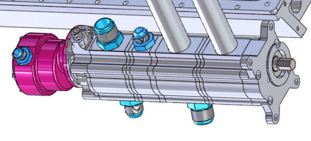
Figure 1: V12 Dry-Sump Oil Pump - Shown with Optional Waterman Fuel Pump
The pressure-regulated flow from the pressure stage goes first to a large capacity oil filter, then to the oil-to-water heat exchanger, then to the engine inlet port, shown in Figure 2.
As briefly described in Part 2, the upper block has five full-length oil galleries that are depicted again here. Figure 2 shows a CAD cross-section of the upper block, taken on a horizontal plane that bisects the main oil feed port.
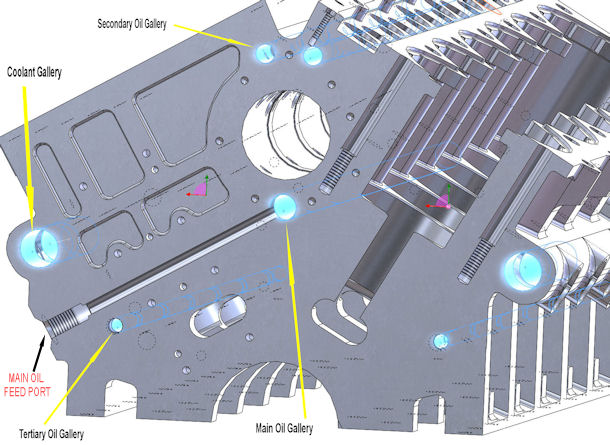
Figure 2: V12 Upper BLock Cross Section
The filtered and cooled pressurized oil enters the block at the Main Feed Port and travels upward to the main oil gallery, which is centered in the block underneath the cam tunnel. The main bearing journals feed directly from this main gallery (the so-called "priority mains" system). The connecting rod journals are supplied from the main journals through angled drillings oriented so as to reduce the centrifugal force component that the con rod oil supply must overcome.
At the flywheel end of the engine, the main oil gallery feeds into the oil distribution plate. That plate channels oil upward to the two secondary (full-length) galleries above the cam tunnel. These secondary galleries supply oil to the cam bearings, the cam followers, through the pushrods and to the rocker arms.
In addition to locating the camshaft axially, the camshaft thrust plate seals off the two secondary galleries and provides a balancing channel between them at the accessory-drive end of the engine.
The oil distribution plate also feeds oil downward to the two tertiary oil galleries that run the full length of the block along the outside of each cylinder bank. These tertiary galleries feed oil to the multiple-jet-per-cylinder piston cooling jets, then upward through passages in the block, up through the heads and into the rocker covers, which contain oil jets that spray cooling oil directly onto each valve spring.
The oil distribution plate contains a control valve that shuts off oil flow to the tertiary system when oil pressure drops below a preset value. Since it is common practice to size the pressure stage of an engine oil pump so as to provide an ‘acceptable’ level of oil pressure under hot-idle conditions (thinnest oil, largest equivalent orifice), then disabling the cooling jets under reduced pressure conditions enables the use of a smaller pressure stage than would normally be required if all the cooling jets flowed all the time.
That shut-off function also provides something of a safety feature, because in the case of an impending bearing failure or other malfunction that would cause oil pressure to drop, the spray jet system will close off, helping to maintain enough pressure to sustain the engine under reduced power and provide more time to get back on the ground.
The piston cooling jets provided a bit of a challenge, both in terms of location to avoid interfering with the moving bits, and the stiffness required to move the cantilever-beam resonant frequency high enough so as not to be excited by basic engine vibrations or their harmonics.
The two engine scavenge stages of the pump draw directly from the sump through O-ringed vertical tubes. These tubes connect internally to each end of an oil collection trough that runs the full length of the right-hand side of the sump (looking at the accessory drive end of the engine). With the crankshaft rotating counter-clockwise from that view, the natural flow of windage oil in the sump is towards the right-hand side of the engine, and the floor of the sump is contoured to promote flow towards the trough.
There is no windage tray because dyno work on other engines has revealed a significant power loss at higher RPM when a windage tray is in close proximity to the rotating machinery.
The gearbox scavenge stage of the pump draws from a screened pick-up near the bottom of the propeller gearbox. All three scavenge stages send the aerated, scavenged oil through the oil tank de-aerators and then into the oil tank reservoir. There is further detail specific to the gearbox lubrication in the Gearbox section.
The oil tank provides several critical capabilities that are necessrary for an all-attitude system. The first and most obvious is the storage of the engine / gearbox oil supply in a place that is isolated form the moving parts. The second is to de-aerate the scavenged oil, which is extremely frothy when it exits the scavenge pump line. The third, and most unique, is the ability to both provide a de-aerated supply of fresh oil to the pressure pump in ANY attitude, and at the same time, to continue the de-aeration function of the return oil in ANY attitude.
This unique tank system emerged from joint discussions with one of my clients (AEROSPORT ENGINEERING). Ole Ringstad, the Chief Engineer there, prototyped the system we discussed, tested it, and made corrections and refinements to it, to the point that it is a geniunely terrific fully-invertted tank system. Figure 3 shows this tank system mounted in the client's S-51 airframe.
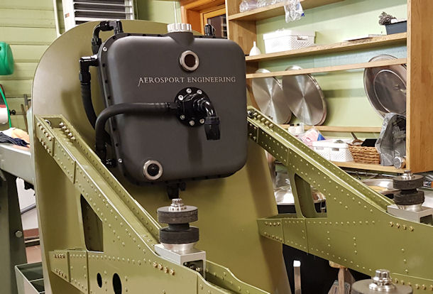
Figure 3: Fully-Inverted Oil Tank System
WET SUMP SYSTEM
The wet-sump version of the engine uses a similar but smaller NRC pump that contains the same pressure stage and regulator, but with a single scavenge stage for the propeller gearbox. The 12-quart engine sump is full-length and baffled, with a centrally pivoted pressure pump pick-up I developed several years ago for cropduster aircraft with V8 power plants.
The wet-sump system has the advantages of less complexity and weight because of fewer components (oil tank, plumbing, scavenge pumps and so on) but it is only suitable for operators who do not intend to fly fully inverted or vertically. It can provide an uninterrupted oil supply in any attitude up to 35° from level in pitch or roll. In coordinated flight, it can operate successfully up to about 80° from vertical in the roll axis. However, it is limited to positive-g maneuvers.
