Part 11: Propeller Gearbox and Accessory Drive
Gearbox Design and Analysis Details
NOTE: All our Products, Designs, and Services are SUSTAINABLE, ORGANIC, GLUTEN-FREE, CONTAIN NO GMO's, and will not upset anyone's precious FEELINGS or delicate SENSIBILITIES.
NOTE: EPI no longer has any involvement in this engine project. Project delays have occurred for a variety of reasons, resulting in conflict between EPI and the client. As a result, the Client-Contractor relationship has been severed by mutual agreement.
I am leaving these pages on the EPI website to describe the engine design details and technology for the general interest of our many readers.
INTRODUCTION
Although the engine accessory drive might seem to be the next logical subject, I am presenting the propeller gearbox first because it covers some important concepts with regard to geared drives in general, which are then applicable to the geared accessory drive.
A propeller reduction gearbox is one of the MOST critical components in a geared Aero engine. The engineering literature is rich with information on the subject of propeller reduction gearboxes.
An American Gear Manufacturer’s Association (AGMA) publication summarises the problem as follows:
“The gearbox is one component of a system comprised of a power source, gearbox, driven equipment, and interconnecting shafts and couplings. The dynamic response of this system depends on the distribution of the masses, stiffnesses, and damping. In certain cases, a system may contain a torsional natural frequency close to an excitation frequency associated with an operating speed. Under these resonant conditions, the dynamic gear tooth loads may be very high, and operation near a system resonance is to be avoided.”
In Volume 2 of his renowned reference work The Internal Combustion Engine in Theory and Practice, (ref-5:3:280) C. F. Taylor says this about propeller gearboxes:
“Particularly complex is a vibration system consisting of an engine with an air propeller mounted on its output shaft, since the propeller blades usually have important modes of vibration which tie in with crankshaft torsional vibration.”
Clearly, a propeller gearbox cannot be treated as an isolated entity. It is a critical component in a vibration-rich system that has two major sources of excitation (the engine and the propeller) and at least two natural frequencies, in addition to the internal natural frequencies of the engine crankshaft system and elements of the propeller itself. Any change to any part of the system can significantly alter the vibratory loadings imposed on the other parts of the system.
THE PROBLEM
Recalling from Part 1 of this series, the instantaneous torsional signature of a spark-ignited piston engine is not a smooth constant-torque line, but rather a waveform that contains significant peaks and valleys above and below the mean (measured) engine output torque.
Figure 1 shows (again) the signature of an even-fire 12-cylinder engine. The amplitudes of the evenly spaced sixth-order torque pulses are roughly ±40% above and below mean torque. Engine configurations having fewer cylinders and/or uneven firing orders produce combinations of lower excitation orders and higher amplitudes, some of which cross below zero torque (torque reversal). The lower orders are more difficult to attenuate.
Examples of those signatures were briefly discussed in Part 1 of this series, and there is a detailed presentation of the subject HERE.
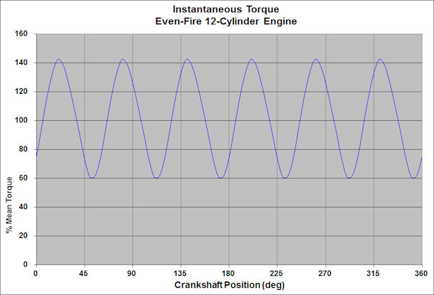
Figure 1: Torsional Signature of Even-Fire V12 Engine
From Figure 1, it is easy to see how the components driven directly by a piston engine would be subjected to torque pulses that can be a significant multiple (+/-) of the mean engine torque, which subjects them and their drive mechanisms to additional cyclic fatigue loading imposed by the varying torque.
It is important to isolate the gearbox and propeller from the torsional pulsing of the engine, for several reasons.
FIRST, gear teeth which are transmitting a pulsing torque curve are exposed not only to the zero-to-peak-to-zero fatigue cycling that would occur if the torque was a constant value, but also to the added rising and falling component of the waveform as it cycles above and below mean torque, and thus to the additional gear tooth contact and bending loads.
SECOND, if the engine excitation is anywhere near a system resonant frequency, the load pulses that are applied to the gears will be multiplied, sometimes by as much as a factor of 10.
THIRD, if the torsional excitation is anywhere close to a resonant frequency of one of the driven components (the connection between the engine and gearbox, the propeller blades), destructive vibrations of those components can be triggered.
As an example, picture what can happen to a propeller blade that is subjected to a pulsing drive torque. During the positive portion of a torque pulse, the blade will deflect in the plane of rotation so as to fall behind its theoretical position, then rebound and spring forward of its theoretical position during the negative portion of the pulse.
If the excitation frequency is close to the natural frequency of the blade, and if the duration of that exposure to resonant excitation is significant, one of the blades will fail in fatigue (probably at the root, but failures have also occurred at various locations along the blade) and depart the aircraft. The resulting out-of-balance will be of such a huge magnitude that it will very likely tear the entire engine off the airframe and likely ruin the pilot’s entire day.
ISOLATION
Isolation from the pulsing drive torque can be accomplished in different ways. Certain compression-ignition engines use a spring-mass system incorporated into the flywheel that is tuned to the excitation frequency of major concern (the ‘dual mass flywheel’). The problem with that approach is that it is only effective at the tuned frequency (and its harmonic multiples).
I think a better approach is to use an engine-to-gearbox coupling that exploits the property of transmissibility, discussed in detail HERE and HERE.
Transmissibility is the ratio of the vibratory force applied to the input of a system to the vibratory force produced at the output of the system. My systems provide an engine-to-gearbox coupling that has very low transmissibility throughout the entire high-power portion of the operating range. That reduces the engine torque pulses to very low amplitudes at all frequencies of interest.
In order to better understand this principle, Figure 2 shows a plot of transmissibility as a function of frequency ratio (r, the ratio of the excitation frequency to the resonant frequency) at different damping ratios (β, the ratio of the existing damping to the critical damping for that system).
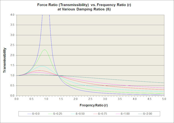
Figure 2: Plot of Transmissibility vs Frequency Ratio for Various Damping Ratios
Figure 2 illustrates three important concepts.
FIRST, in a driven system with zero damping that is operating at the resonant frequency, the transmissibility (force ratio) goes to infinity. If you add a substantial amount of damping to the system, nevertheless, at frequencies near resonance the transmissibility is always greater than one, which means that the input forces are being amplified, sometimes by a very large amount. In practical systems, the transmissibility rarely goes to infinity because nearly all the components possess some amount of internal damping.
SECOND, at a frequency ratio above 1.414 (‘crossover’), the force ratio drops below 1.0, and at a frequency ratio above 3.3 with zero damping, the transmissibility drops below 0.10. Therefore the amplitude of the vibratory forces transmitted to the gearbox is attenuated to below 10% of the engine excitation amplitude, and that fraction can approach 1% at higher frequency ratios.
THIRD, it is clear that damping needs to be minimized in order to achieve the very low transmissibility values that reduce engine excitation to a mere ripple.
The principles outlined here show that by moving the crossover point to as low a frequency ratio as practical, and by minimising the damping in the system, the transmissibility at high frequency ratios can become very low (less than 0.05) and the driven load becomes isolated from the vibration induced by the engine.
Damping is a crutch that is effective at reducing driven vibrations IF one must operate below crossover. However, above crossover, the low transmissibility cannot be achieved if there is any significant damping in the system.
Note: the term ‘damping’ is frequently misunderstood. The property of “damping” enables a system to dissipate energy, usually by conversion of kinetic (motion) energy into heat energy.
The misnamed automotive device known in parts of the world as a shock absorber is a common example of a damper (and is known as a damper in the UK and elsewhere).
If you push on the ends of a fully extended “shock absorber” (so as to collapse it), the rod moves into the body at a velocity that is related to how hard you are pushing. Double the force and the velocity doubles (except in tricky race-engineered dampers). When the damper is fully collapsed, and you release your hand pressure, the rod does not spring back out – no energy has been is stored. The energy (the force applied over a distance) expended to collapse the damper has been converted into heat, which is dissipated through the walls of the shock absorber.
THE SOLUTION
The engine-gearbox-propeller system can be simplified into a two-degrees-of-freedom system [Figure 3] consisting of three flywheels and two shafts.
The "Equivalent Engine" flywheel has the effective mass moment of inertia (EMMOI) of the complete engine at the flywheel end of the crankshaft, including anything attached to that end of the crankshaft. The "Equivalent Gearbox" flywheel has the composite EMMOI of the gearbox (input, idler and output gears and shafts). The "Equivalent Propeller" flywheel has the EMMOI of the driven load, methematically referred back to the engine through gear ratio. (For those who slept through high school physics class, "mass moment of inertia" can be visualized as "flywheel effect".)
The first shaft has the net torsional rate of the connection between the engine and gearbox, and the second shaft has the net torsional rate of the connection between the output gear and the propeller system.
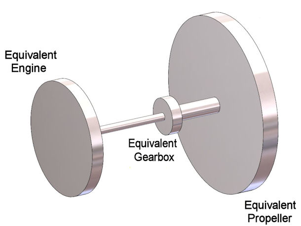
Figure 3: Equivalent Vibrating System
The mathematical solution for the two resonant frequencies is fairly straightforward. Many years ago, I wrote a program to calculate the relevant EMMOI and torsional rate values from properties of the real components, then solve for the first and second mode resonant frequencies of the system.
Those solutions enable an iterative design process in which I adjust the component properties so as to achieve the design target frequencies and stress levels, then try to design components that actually have those properties.
In practical terms, the goal is to move the first mode resonant frequency to below the engine excitation frequency at engine idle, and move the second mode to at least twice the excitation frequency at maximum propeller RPM.
It would be ideal to move the second mode to below engine idle as well, but the resulting physical properties of the gearbox elements would be entirely unsuitable to support propeller thrust, driving torque and gyroscopic moment loads.
Achieving the desired first and second mode resonant frequencies is achieved by tailoring engine EMMOI and the torsional rates of the input and output shafts.
The reduction ratio has a strong influence on the solution because the actual masses and rates of the driven components (propeller, shafts and gears) are reduced by the square of the reduction ratio (19/60 in this case) to establish the equivalent values in the simplified model (Figure 3).
Figure 4 shows a plot of the transmissibility of the V12 in race configuration with the most-likely propeller and assuming a damping ratio of 0.15. Above 1950 RPM, the transmissibility is below 0.10; above 4900 RPM it falls below 0.03.
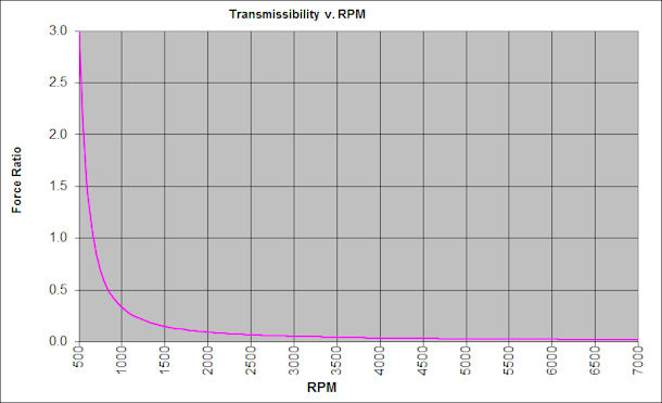
Figure 4: Transmissibility for the V12 Powerplant in Race Configuration
I have been able to achieve the required strength and torsional rate in the engine-to-gearbox connection by the use of shafting made from an extreme-strength alloy using a proprietary heat treatment process to achieve a tensile strength of 290 ksi, a yield strength close to 240 ksi, and fracture toughness that substantially exceeds steels used for oil-well drilling bits.
That design provides extreme torsional strength while enabling suitably low torsional rates needed for vibration isolation. The required engine EMMOI is achieved by means of a bespoke flywheel design that provides high MMOI values with a relatively low overall weight.
Note that for the even-fire V12 engine shown in Figure 4, the sixth-order excitation at crossover (approximately 700 RPM) is at a frequency of 70 Hz. If the engine was an even-fire six-cylinder, that 70 Hz crossover would occur at 1400 RPM. That comparison shows the increasing difficulty of fully attenuating lower excitation orders.
GEARS
Gearbox purveyors often advertise the horsepower that their unit is claimed to handle. However, the power which is transmitted through a gearbox is only of interest for determining heat rejection (cooling) requirements, and is essentially meaningless in terms of the loads applied to the internal components.
The torque applied to the input gear in a gearbox is the value that establishes the force applied to the faces of all the other gear teeth in a geartrain. For example, applying a constant torque of 1600 lb.ft. to a 19-tooth, 5-DP input gear (3.8 in pitch diameter) produces a pitchline contact force on all contacting teeth in the geartrain of 10,108 lb. Torque pulses can easily double or triple that number. Resonant vibration can easily multiply it by 10.
That is one of the main reasons why it is essential to reduce the gearbox input waveform to as close to a flat line as possible, by reducing the transmissibility value to near-zero in the operating range.
DYNAMIC GEAR LOAD
One aspect of gear loading which is commonly ignored, but critically important, is the phenomenon known as dynamic gear load. That is a condition that can increase the forces on a pair of contacting gear teeth far beyond that which would be applied by the input torque alone.
Dynamic gear loading begins when a pair of teeth is just coming into mesh. Assume for the moment that we have a pair of gears that have been manufactured so accurately that the location and profile of every tooth is absolutely perfect. With such perfection, one might think that each successive tooth pair would pick up the load perfectly smoothly as the teeth enter the mesh.
Not so, however.
First, visualise the tooth-mesh when a single pair of teeth is carrying all the load. If the load is significant, those two loaded teeth have deflected from their unloaded (‘theoretically perfect’) positions. That deflection allows the rest of the driving gear to move slightly ahead of its theoretical undeflected position, and allows the driven gear to lag slightly behind its theoretical undeflected position. Those slight deflections cause all the unloaded teeth on both gears to move slightly out of their correct positions with respect to the tooth-pair carrying the load.
Because of that deflection, when the next tooth-pair comes into mesh, they touch each other sooner than they would if there had been no deflection, thus they pick up a disproportionate amount of the load very quickly.
That sudden load application produces a hammer-like force (impact) which can cause the teeth to bounce apart (just as a hammer will rebound from striking a hard piece of steel) then re-contact later in the mesh, causing another impact. The forces seen by the teeth during these impacts can be much greater than the load applied by the transmitted torque.
Added to that problem is the fact that it is not possible to manufacture theoretically perfect gear teeth. As the errors in tooth location and profile increase, the magnitude and randomness of the dynamic load increase as well.
The determination of the dynamic loads is a complex methodology. It takes into account factors which include gear tooth manufacturing tolerances, tooth stiffness, torsional rates of all loaded shafts and gears, and mass moment of inertia values of the engine, connecting shafts, gears and the driven load.
That dynamic load methodology is described in detail in the published works of gear technology pioneers Earle and Elliot Buckingham (Library Section 2, Volumes 11 and 12). Volume 12 includes the calculations for static and dynamic tooth bending and contact stresses, stress concentrations as a function of tooth root radius, and depth of maximum shear.
I used the methodologies from their books as the basis for a computer program that calculates those loads and stresses, and estimates fatigue life for various configurations of gear drives. That allows me to adjust various parameters in the system to reduce the dynamic-to-static load ratio (Wd / Ws) to (typically) less than 1.10.
GEAR FATIGUE
Regarding fatigue life, I use the term estimate because the mathematics of fatigue are largely statistical and involve the use of safety factors derived from successful field experience.
Typical heat-treated steels exhibit a property known as the endurance limit, which represents a theoretical cyclic stress level that the material can withstand for an ‘infinite’ number of cycles.
The “endurance limit” is commonly defined as the amplitude of the fully-reversing cyclic stress that the sample material can survive for 107 cycles.
However, the case-hardened steels that are commonly used in highly-loaded gears (carburised 8620 and 9310) do not exhibit an endurance limit. That makes long-life gear design an even greater challenge.
The use of the combined technologies of isolating the gears from the engine vibration and of minimising tooth dynamic load has enabled me to use rather small gears successfully in various propeller gearboxes. One model had a 1.5 in-wide, 6 DP, 21-tooth input gear (3.500 in pitch diameter), and could handle over 600 lb.-ft. of input torque virtually forever at very modest stress levels. One of those gearboxes raced successfully at Reno for several years.
The gears for the race version of our V12 are 2 inch-wide, 5 DP gears that implement a 3.16 ratio and have a predicted life of over 1000 hours at an input torque of 1600 lb-ft. The Wd/W for the driving gear is 1.027, and for the driven gear it is 1.096.
Figure 5 shows the 12.4-inch diameter output gear for that gearbox.
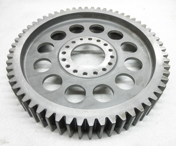
Figure 5: Output Gear for Race V12 - 1600 lb-ft Long-Life Torque Capacity
Regardless of the imagined superiority of helical gears, all my gearboxes use spur gears. That practice follows several highly successful propeller gearboxes such as the Rolls-Royce V-1650 Merlin, the Allison V-1710, most of the Pratt & Whitney radials, the Continental GTSIO-520 and -550 engines, as well as the Garrett TPE-331 and Pratt & Whitney PT-6 turbines.
Spur gears are less expensive to make, do not suffer from the edge-loading problems that arise from not having a precise match of helix angles on mating gears, and do not produce the considerable axial forces that helical gears generate.
Helical gears have occasionally been used to implement a mechanical torque sensing system by the conversion of the axial gear load into a hydraulic pressure. They were also used in a very clever torque-balancing mechanism between the two crankshafts in the Napier Sabre (H-24 WW2 aircraft engine), and (as was recently revealed to me by an expert) used in a clever hydraulically-opposed system to achieve full load-sharing and torque sensing in the 3-pinion planetary reduction in the Rolls-Royce Dart turboprop engine.
Helical gears are also useful to transmit power between shafts that have non-parallel axes, such as are used to drive the distributors and oil pumps from the camshafts in countless automotive applications. Those implementations are known as 'crossed helicals'.
They offer a significant challenge in design that is different from helical gears on shafts with parallel axes. Gears on shafts having parallel axes have a theoretical line-contact between driving and driven teeth. However, crossed helicals have a theoretical point-contact between driving and driven teeth, which applies a huge contact stress to the teeth in spite of relatively low applied loads. In order to survive a relatively low transmitted force value, the modulus of elasticity of the materials used in crossed helicals must be low enough to allow elastic deformation at the point of contact so as to increase the contact area enough to reduce the contact stress to a survivable level. I use crossed helical gears in my gearboxes to implement the governor drive mechanism.
The propeller gearbox for this engine uses a torsionally-isolated crossed helical drive to run the propeller governor, which contains several rotating parts and a 300 psi hydraulic boost pump.
Other than those specialized applications, as far as I am concerned, the only virtue of helical gears is they are quieter than equivalent spur gears, but in racecars and aircraft, gear noise hardly matters.
BEARINGS AND LUBRICATION
All the bearings in our V12 propeller gearbox are pressure-fed hydrodynamic bearings. That allows a very high level of load capacity without the extreme size and weight penalties that would result from rolling element bearings having similar capacities. For example, the gearbox hydrodynamic thrust bearings can easily accommodate thrust forces in excess of 3000 lb in either direction.
The gearbox lubrication / cooling system uses pressurised, filtered and cooled engine oil. That has been proven to be effective for decades, going back to the original Mini Cooper with the crosswise engine that had the gearbox in the crankcase. It has also proven to be effective with several different versions of my gearboxes, with the added advantage of reducing cooling drag by relying on only one heat exchanger for the cooling of all the oil in the propulsion system.
Pressurised oil is fed to the bearings through internal galleries, and is strategically directed at the exiting-mesh area of the gear teeth by jets, coupled with copious splash lubrication from the hydrodynamic bearing run-off. A dedicated section of the engine oil pump scavenges the gearbox oil and returns it to the oil tank.
PROPELLER CONTROL
The gearbox includes the standard AND-20010 propeller governor interface, with a torsionally-isolated gear drive and fully internalized hydraulic plumbing. The governor contains a boost pump that increases the supply oil pressure to about 250-300 psi for operating the propeller pitch control piston.
The propeller governor changes the pitch of the propeller blades in response (a) to pilot command, (b) to any change in propeller load, and (c) to any change in engine power.
The pilot sets a desired propeller RPM with the propeller control lever. The governor changes the pitch of the propeller so that it turns at the requested RPM with the existing level of power being produced by the engine. If engine power changes (pilot moves the throttle) or propeller load changes (gust loads and aircraft maneuvering), the governor changes the pitch so as to maintain the set RPM.
The governor senses propeller RPM by means of a set of spinning flyweights. Those flyweights push on one end of a hydraulic metering valve. The flyweight force is opposed by a spring at the other end of the valve. The load of that spring is set by the pilot’s propeller control lever. The position of the pilot valve is determined by the force-balance between the flyweights and the spring, and thus determines the proportion of the boost pump pressure that is applied to the pitch control piston at any given time. Exquisitely simple and reliable.
HOUSINGS
The gearbox housing system consists of three sections: the front gear housing, the rear gear housing and the bellhousing, which can adapt the gearbox to any one of several different engines. All three sections are CNC-manufactured from high-strength aluminium billet material. The system has been designed to provide the strength and stiffness required by the combination of gear separation loads, thrust loads, g-loads, and the large gyroscopic moments that result from rapid changes in angular velocity in the pitch or yaw axes. Figure 6 shows the gearbox housing set.
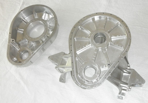
Figure 6: Propeller Gearbox Housing Set - CNC from High Strength Aluminum Billet
Extensive FEA work on the housing set has helped achieve the targeted very low deflection characteristics, which yielded relatively low stress values, even at extreme conditions.
Figure 7 shows the stress FEA of the housing set with 1600 lb.-ft. of applied input torque, 4980 lb-ft of opposing propeller drive torque, 3000 lb of thrust, 2900 lb.-ft. of propeller gyroscopic moment, 3626 lb of gear separation load on each shaft, and the mount loads resulting from a 3g vertical acceleration on the entire powerplant. The results show a peak stress of 11,000 psi and a peak deflection of less than 0.003 in (in the mounting ears).
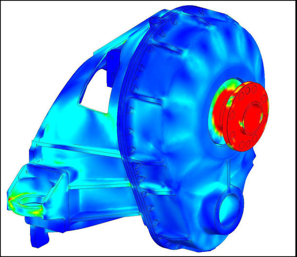
Figure 7: FEA of Housing Set under Combined Large Loads
Figure 8 shows the FEA the FEA of the propeller shaft with 4980 lb-ft of propeller torque, 3000 pounds of thrust, 2900 lb-ft of propeller gyroscopic moment, and 3626 lb of gear separation load applied. The results show a peak stress of 101,000 psi in the fillet just behind the prop flange, which is suitably below the material endurance limit.
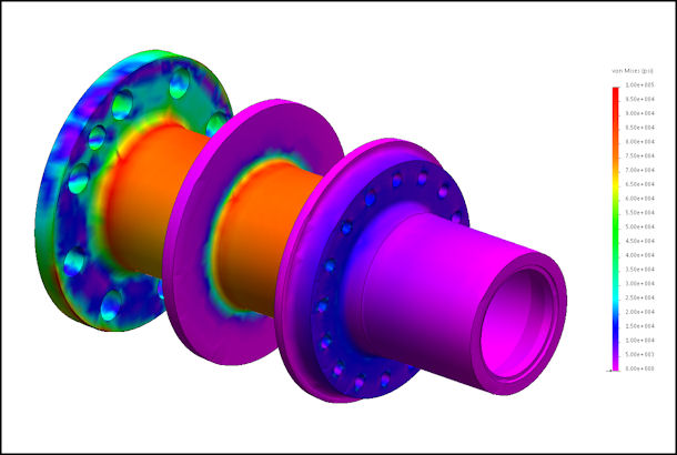
Figure 8: FEA of Propeeller Shaft Under Combined Large Loads
ACCESSORY DRIVE
The V12 accessory drive system includes the camshaft drive, the drives for the two alternators, the engine oil pump, a hydraulic pump for aircraft landing gear systems, a vacuum pump for aircraft instrument systems, and the two coolant pumps.
This system is driven by a gear on the crankshaft free end. The crankshaft torsional vibrations at the free end are attenuated by an ATI spring-mass absorber tuned to the major excitation frequency.
As mentioned, the disadvantage of that type of attenuator is that its peak effectiveness is limited to the vicinity of one frequency, typically where an excitation harmonic and a crankshaft resonant frequency coincide. In an even-fire engine, the major torsional excitations occur at the primary order (the sixth, in the case of this engine), but higher harmonics can be important as well.
The need to reduce the amplitude of the excursions throughout the operating range will eventually lead to the incorporation of a true sixth-order absorber using the pendulum absorber principles (described HERE to implement torsional absorbers that are tuned to an order, and thus are effective across the entire RPM range.
In the naturally aspirated and turbocharged engine versions, the accessory drive contains nine hardened alloy-steel gears. The accessory gear system contains a primary torsional isolator fashioned after the Cosworth Formula One design. It provides a torsional rate of approximately 400 lb-ft per degree and, together with the combined MMOI of the coolant pumps, oil pumps and alternators, it reduces the transmissibility of the system to below 0.3.
The incompressibility of the pumped fluids has the effect of adding a significant “equivalent” moment of inertia to the driven system. In addition, the alternators and coolant pump rely on the tailored torsional stiffnesses of their driveshafts to accomplish further isolation. As a result, the worst Wd/W ratio in the accessory drive is 1.13.
All the gears (except the crankshaft and camshaft gears) are supported by rolling element bearings located in the block and the accessory case.
The accessory drive system for the supercharged version includes an additional seven gears to provide up to 175 hp to the supercharger at the correct compressor speed. Two of those seven gears also comprise the dedicated torsional absorber that isolates the supercharger and gearing from torsional excitation.
Figure 9 shows the accessory drive internals for the turbocharged and naturally aspirated versions of the engine.
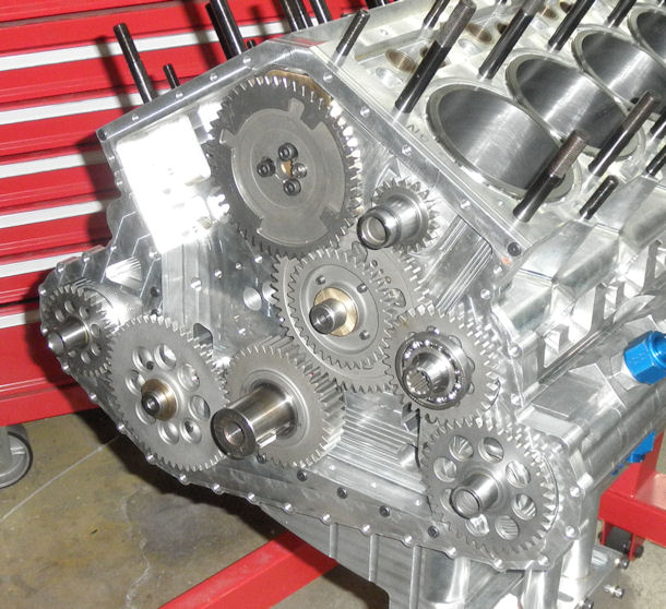
Figure 9: Accessory Drive Gears for NA and Turbo Engines
As shown in Figure 9, there are several gears in the system that are driven by one gear and that also provide drive to subsequent gears (‘idlers’). The teeth of an idler gear are subjected to the most severe kind of fatigue loading – fully-reversing bending loads. The driving gear applies a bending load to the idler teeth in one direction, then when the idler teeth contact the driven gear, the same (in the case of a pure idler) or lower (in the case of an idler that also drives a device) bending load is applied on the opposite direction. The bending load and root stress magnitudes for any idler gear must therefore be accurately calculated, and the design of the gear must provide for a suitably lower endurance limit.
Figure 10 shows the fully populated accessory drive for the naturally aspirated and turbocharged versions.
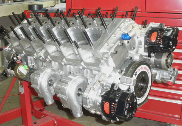
Figure 10: Fully-Populated Accessory Housing
