- Crankshaft Torsional Absorbers -
Often mistakenly called "crankshaft harmonic dampers"
NOTE: All our Products, Designs, and Services are SUSTAINABLE, ORGANIC, GLUTEN-FREE, CONTAIN NO GMO's, and will not upset anyone's precious FEELINGS or delicate SENSIBILITIES
The previous page of this section addressed the issue of the torsional excitation which a piston engine applies to whatever device it is driving. However, there is the separate issue of the torsional vibration of the crankshaft itself within the engine.
The subject of crankshaft torsional vibration and its importance is an area in which the key NASCAR Cup and F1 players are very reluctant to discuss specifics. However, based on discussions with several crankshaft design wizards, it appears that there is quite a wide divergence of opinion on the subject of how best to deal with crankshaft torsional vibration.
A crankshaft, like a plain torsion-bar, has mass and a torsional spring rate (see Torsional Vibration). That causes the crankshaft system to have its own torsional resonant frequency. The torque peaks and valleys plus the inertia loads from the acceleration of the reciprocating components cause the engine crankshaft itself to deflect (rotationally) forward and backward while it is operating. When those pulses (excitations) are near the crankshaft resonant frequency, they can cause the crank to vibrate uncontrollably and eventually break.
Understand that the resonant frequency of the crankshaft system is different from the resonant frequencies encountered in the PSRU system. The torsional resonant frequency of the crankshaft system is a function of :
- crankshaft length;
- crankshaft torsional stiffness;
- crankshaft stroke;
- bobweight mass;
- moments of inertia of rotating items attached to or driven by the engine.
It is well known that excitation of any component at or near one of its resonant frequencies will, in the absence of either substantial damping or opposing oscillation, cause the amplitude of the oscillation to increase without bound until the component fails. There are famous films showing bridge failures from exactly this phenomenon.
Here are a few definitions (discussed in greater detail HERE) which will be helpful for this discussion.
- A FREQUENCY is exactly what the word suggests: vibration at a specific number of cycles per second, as in 400 cycles per second ("hertz"), or how frequently the oscillation occurs.
- An ORDER is a specific multiple of a basic frequency. For example an even-firing eight-cylinder, four-stroke engine produces four torque pulses per revolution (a fourth order excitation). If the crankshaft in such an engine was operating at 6000 RPM, then the frequency of the fourth order excitation is 4 x 6000 / 60 = 400 hertz whereas the same 4th order excitation at 7200 RPM is a frequency of 480 hertz.
- A DAMPER is a device which dissipates energy, mainly in the form of heat.
- An ABSORBER is a device which is designed to oscillate in direct opposition to a vibration at either a specific frequency or a specific order, depending on the design.
A crankshaft made from a lump of high-strength steel is nearly a perfect spring, and it contains very little inherent damping, so it becomes important to provide some means of attenuating the torsional oscillations which occur near resonant frequencies, especially at the free end of the crankshaft.
Many engines, including virtually all V8’s, V6’s and inline 6’s, use a device on the free end of the crankshaft to attenuate the amplitude of what could otherwise become destructive torsional oscillations of the crank. Without an appropriate absorber, the life expectancy of the crankshaft in a typical American V8 engine at full power can usually be measured in minutes. (The flywheel-less Sprint Car V8 engines with the water pump attached to the nose of the crankshaft are indeed a special case by virtue of the substantial alteration in natural frequencies by the lack of a flywheel, coupled with the natural damping effect of a water pump.).
Many of the automotive 4-cylinder engines don’t require such an absorber, primarily because of their inherently higher stiffness-to-mass ratios. However, several automotive manufacturers have initially omitted a torsional absorber from early engine runs, only to find that crankshaft life was unacceptably short. The Nissan folks discovered this with the early 240-Z engines, which didn’t have an absorber, and therefore lasted only about 100 hours in automotive (i.e. VERY LIGHT DUTY) service.
Often, the vibration attenuating devices on the free end of an engine crankshaft are incorrectly referred to as "DAMPERS". In most cases, they are ABSORBERS.
The elastomeric ("metal-ring-on-rubber-spring") devices used by the automotive industry (as well as by Teledyne Continental Motors on the GTSIO-520) are ABSORBERS which are tuned to counteract vibration at the frequency where the particular engine generates its worst torsional excitation. There is a certain amount of hysteresis in the bonded elastomers of production-style absorbers which adds a small amount of damping to the system.
The O-ring elastomers in the tunable inertia ring - elastomer style damper used in Cup and other classes are quite small in both cross sectional area and contact surface area, so the damping coefficient is rather limited. The small contact surface area, combined with the large amount of enerdy to be dissipated over an extended time period in a very hot environment, requires that these absorbers be rebuilt frequently in order to maintain their effectiveness. That same manner of degradation effects OEM-style elastomeric absorbers, but to a much lesser degree because of the infrequent combination of operating at or near the resonant frequency with high power settings in a very hot ambient environment.
By design, this style of absorber has a single resonant frequency, which is tuned by means of the MMOI of the inertia ring and the durometer (stiffness) of the elastomers to the specific frequency (crankshaft RPM times excitation order) at which measurements have shown the crankshaft vibration amplitude to be the worst.
Unfortunately, there is often more than one strong excitation order. Current science shows that the predominant excitation in a two-plane V8 crankshaft is the 2.5 order, followed next by the (more intuitive) 4th order. It has been suggested that there is a new development in the inertia-ring - elastomer style damper used in Cup which provides the ability to tune for more than one critical frequency.
In addition to the elastomer style of absorber, there is a type of absorber which by design, attenuates a particular order of vibration. This style is known as a pendulum absorber, and was developed in the nineteen thirties to solve serious torsional vibration problems in radial aircraft engines. Both Continental and Lycoming use this style of pendulum absorber in all their high-output engines.
This style of internal absorber consists of pendulous counterweights attached to the crankshaft cheeks by loose pins in hard bushings, as shown in Figure 1. It is a tuned absorber whose natural frequency is directly proportional to the rotational speed of the crankshaft. The tuned order is determined by the ratio (r/L), the distance from the main bearing centerline to the pendulum pivot, divided by the pendulum length. The typical implementation is by means of attaching the crankshaft counterweights to blades on the crankshaft webs by means of hardened pins in loose bushings. The tuned order (r/L) is determined by the clearance between the hardened pin and the hardened bushing in the crankshaft blades. The mathematics of this type of absorber are fiendishly clever, and presented in great detail in ref-5:3:284-288.
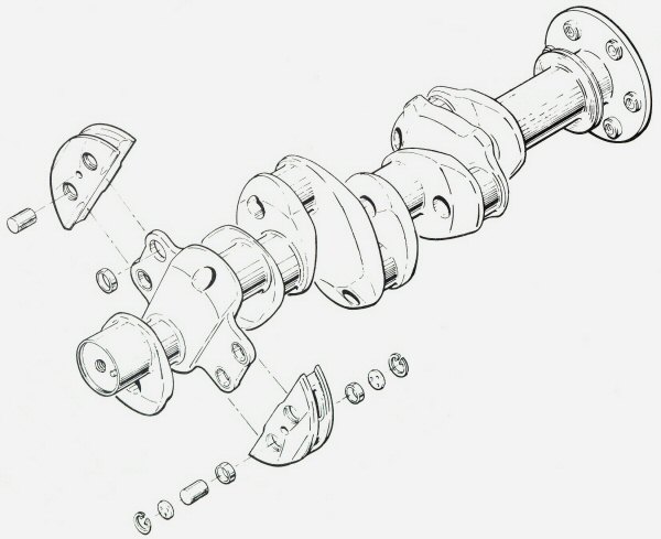
Figure 1
Pendulum-Style Order-Absorbers
There is an aftermarket product (The Rattler™) which attempts to implement this method of order-absorption by means of heavy-metal cylinders which fit inside appropriately-sized longitudinal cylindrical bores in a round device attached to the nose of the crankshaft.
Considering that the aircraft style pendulum counterweights shown above weigh several pounds, one cannot help but question just how effective the rattling style device can be. However, it would seem that an approach more similar to the aircraft example might be found to be quite effective without adding substantially to the crank MMOI. Another approach might be to incorporate large loose heavy-metal cylinders into sized longitudinal drillings in the existing counterweights.
In contrast to an absorber, the advantage of a pure damper is that it will tend to reduce the amplitude of any frequency. The disadvantage is that the energy is dissipated as heat, so a suitable amount of cooling must be provided.
There are frictional dampers as well as inertia-ring-in-high-viscosity-fluid dampers available in the aftermarket. Testing has shown that those types of dampers vary in effectiveness, depending on the frequency, but that their effectiveness is fairly even over a wide range of excitations. Unfortunately, they are significantly less effective in reducing vibration in a specific, targeted frequency range, the exact situation you have in an aircraft engine. (There is ample research in the engineering literature showing exactly that fact.)
One aftermarket device, the Fluidampr™, is an example of a damper. It contains an inertia ring surrounded by a very high viscosity fluid. Vibratory energy is dissipated by transforming it into heat, generated by the shearing action between the inertia ring, th fluid, and the outer containment. The published results of testing by the manufacturer and by other users show that typically the Fluidampr™ is increasingly effective at higher engine speeds.
That makes the Fluidampr™ attractive to engine builders in many forms of auto racing. It can be especially valuable when the natural frequency of the crankshaft system has been substantially altered. Any large change in the crankshaft system natural frequency can render the original tuned elastomeric absorber ineffective, because the inertia mass the effective torsional rate of thr elastomers were developed to make the original absorber tune to the peak excitation frequency of thje original engine configuration.
Typical engine-builder modifications that can significantly alter the crankshaft torsional resonance point include (a) different crankshaft torsional stiffness (longer or shorter strokes, different bearing journal diameters, etc), (b) lighter reciprocating components which have dramatically reduced the effective "bobweight", (c) lighter clutch and flywheel components, (d) removal or addition of accessories driven by the crankshaft free end, and others.
Some time ago, this product had been banned from the top levels of NASCAR racing, reportedly because extended use at high levels of energy dissipation, coupled with extremely restricted cooling airflow, prevented the heat energy from being effectively dissipated. The resulting heat reportedly caused the polymers in the shearing fluid become rearranged, changing the base viscosity and allowing the fluid and the mass ring to settle off-center when the engine stopped. The next time such an engine was run, the nose of the crank would be horribly out of balance, and there's a short run from there to cranksaft failure.
In order to remedy that problem, the manufacturer devised an internal system that retains the inertia ring in the centered location. The revised system has reportedly been successfully tested by more than one NASCAR Cup engine company.
All that being said, one might reasonably ask the question: "If this is such a big issue, why do I not see absorbers on the noses of Formula One crankshafts?" The glib answer I got from one expert was "Because they are not appropriate".
Here are a few reasons they might not be appropriate. First, the peak torque of a contemporary Formula One engine is roughly 220 lb-ft whereas the torque peak of a contemporary Cup V8 is approximately 520 lb-ft. Therefore, the instantaneous combustion force imposed on a Formula One crank is likely in the realm of 2.25 times smaller than that on a Cup crank. Second, the lever arm (half-stroke) of a Formula One crankshaft is about 0.78 inches (19.9 mm) whereas the lever arm of a 3.25-inch stroke Cup crank is 1.625 inches (41.3 mm). Therefore, the Formula One instantaneous vibratory torque is much smaller. Third, the Formula One crankshaft is far stiffer torsionally, being somewhat shorter and having about 0.89" (22 mm) of crankpin overlap compared to about 0.300" (7.7 mm) of overlap on a Cup crank. Thus the torsional stiffness relative to the loading is much higher, and the torsional resonant frequency is also much higher.
The fact that a Formula One crankshaft is running through a wider RPM band and doing so rather quickly suggests that the crankshaft doesn't spend much time at any critical frequency. (That same ‘quick transition’ argument might also well apply to sprint-car and drag race engines.)
Some experts say that the bigger issue with crankshaft torsionals in a Formula One engine is the level of excitation into the valvetrain, which detracts from the accuracy of valve motion. There are various ways to reduce the torsionals being transmitted into the cams, which include tuned absorbers in the valvetrain drive system, in the form of quill shaft torsion bars having an appropriate torsional spring rate, as well as pendulum absorbers on the camshafts. There are also torsional rate devices that use gears having circumferentially-oriented helical springs and a movable center (same concept as the spring center on a conventional clutch disc.)
One crankshaft manufacturer described torsional absorbers / dampers as "a great hoax", based on two observations he has made in his experience: (1) A crankshaft which has an absorber tuned to the wrong frequency has a very short life expectancy, and (2) Certain aftermarket absorber / damper products installed on a crankshaft pose extreme difficulties in balancing the assembly.
It is obvious that modifications to an original engine design which affect crankshaft stiffness and / or system MMOI (stroke, counterweights, bobweight {therefore counterweight} mass, clutch and flywheel MMOI, etc) will change the system resonant frequency. In order to determine the correct solution for a particular engine combination, the engine designer must a) do the measurements to determine the critical frequencies in your application and (b) and design or obtain an absorber tuned for the correct order or frequency, as fits with the application.
For any application which operates at high power and a relatively constant speed for long periods (unlike a race engine which typically cycles up and down quite rapidly and only has to live a few hours), it is critical that the major orders of crankshaft torsional vibration be attenuated.
Whatever device is used to absorb crankshaft internal torsional vibrations, it has an effect (usually small) on the excitation produced at the loaded end of the crankshaft around resonance. That device, together with the Mass Moment of Inertia of the devices attached to the output flange of the crankshaft, will affect not only the value of the crankshaft resonant frequency, but also will influence the longitudinal location of the torsional node on the crankshaft.
