- Contemporary Crankshaft Design -
Design, Materials, Manufacturing
NOTE: All our Products, Designs and Services are SUSTAINABLE, ORGANIC, GLUTEN-FREE, CONTAIN NO GMO's, and will not upset anyone's precious FEELINGS or delicate SENSIBILITIES
THIS IS AN EXPANDED VERSION OF AN ARTICLE
BY Jack Kane WHICH APPEARED IN ISSUE 033 of
RACE ENGINE TECHNOLOGY MAGAZINE
This page describes the important aspects of crankshaft design and implementation. Having a good understanding of the Basics of Piston Motion wll assist in the full understanding of some of the concepts presented here.
INTRODUCTION
A crankshaft contains two or more centrally-located coaxial cylindrical ("main") journals and one or more offset cylindrical crankpin or ("conrod") journals. The two-plane V8 crankshaft pictured in Figure 1 has five main journals and four conrod journals, each spaced 90° from its neigbors.
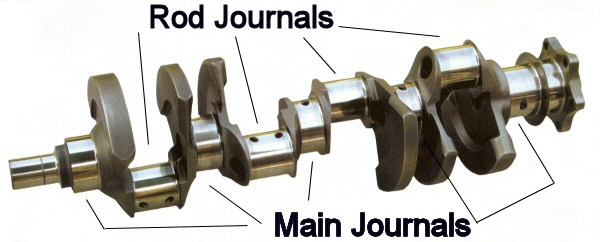
Figure 1: Example (2-plane) Crankshaft
The crankshaft main journals rotate in a set of supporting bearings ("main bearings"), causing the offset conrod journals to rotate in a circular path around the main journal centers, the diameter of which is twice the offset of the conrod journals. The diameter of that path is the engine "stroke": the distance the piston moves up and down in its cylinder. The big ends of the connecting rods ("conrods") contain bearings ("rod bearings") which ride on the conrod journals. (For details on the operation of crankshaft bearings, Click Here; For important details on the motion which the crankshaft imparts to the piston assembly, Click Here )
FORCES IMPOSED ON A CRANKSHAFT
The first source of forces applied to a crankshaft is the product of combustion chamber pressure acting on the top of the piston. High-performance, normally-aspirated Spark-Ignition (SI) engines can have peak combustion pressures in the 120 to 130 bar neighborhood, while contemporary high-performance Compression-Ignition (CI) engines can see peak combustion pressures in excess of 200 bar.
A pressure of 120 bar (1740 psi) acting on a 4.00 inch diameter piston wil produce a force of 21,866 pounds. A pressure of 200 bar acting on a 4.00 inch diameter piston produces a force of 36,442 pounds. That level of force exerted onto a crankshaft rod journal produces substantial bending and torsional moments and the resulting tensile, compressive and shear stresses.
There is another major source of forces imposed on a crankshaft, namely Piston Acceleration. The combined weight of the reciprocating components (piston, ring package, wristpin, retainers, the conrod small end and a small amount of oil) is being accelerated from zero to a very high velocity and back to zero velocity twice each crankshaft revolution. This velocity characteristic and the associated accelerations which that motion produces, are presented in detail on the page entitled PISTON MOTION BASICS.
Since the force it takes to accelerate an object is proportional to the weight of the object times the acceleration (as long as the mass of the object is constant), many of the significant forces exerted n those reciprocating components and on the wristpin, conrod, crankshaft, crankshaft, bearings, and engine block are directly related to piston acceleration. A more detailed discussion of those loads and vibrations they can cause is presented on the page entitled FORCES ON RECIPROCATING COMPONENTS.
In addition to these reciprocating forces and the resulting moments, there is a rotating mass associated with each crankpin, which must be counteracted. The rotating mass consists of the weight of the conrod big end(s), conrod bearing(s), some amount of oil, and the mass of the crankshaft structure comprising the crankpin and cheeks. These rotating forces are counteracted by counterweight masses located in appropriate angular locations opposing the conrod journals. Figure 2 shows a single-plane V8 crankshaft, in which the counterweights are directly opposite their associated rod journal. A fully-counterweighted inline-4 cylinder engine has a similar layout.
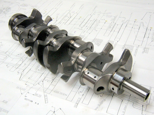
Figure 2: Single-Plane V8 Crankshaft (Courtesy of Bryant Racing)
However, the counterweights are not always directly opposite the rod journals. For example, the commonly-used production version of a two-plane 90° V8 crankshaft has no counterweights around the center main journal, as shown in Figure 1 above. In that case, the centroid of each counterweight, instead of being 180° from its respective journal, is offset (to approximately 135°) in order to place the net counterbalancing forces in the optimal location. Note also (in Figure 1) that the front and rear counterweights are larger (thicker) than the others in order to fully counterbalance the end-to-end moments.
CRANKSHAFT MANUFACTURING PROCESSES
Many high performance crankshafts are formed by the forging process, in which a billet of suitable size is heated to the appropriate forging temperature, typically in the range of 1950 - 2250°F, and then successively pounded or pressed into the desired shape by squeezing the billet between pairs of dies under very high pressure. These die sets have the concave negative form of the desired external shape. Complex shapes and / or extreme deformations often require more than one set of dies to accomplish the shaping.
Originally, two-plane V8 cranks were forged in a single plane, then the number two and four main journals were reheated and twisted 90° to move crankpins number two and three into a perpendicular plane. Later developments in forging technology allowed the forging of a 2-plane "non-twist" crank directly (Figure 3).
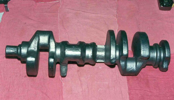
Figure 3: Two-Plane V8 Crankshaft Raw Forging
Crankshafts at the upper end of the motorsport spectrum are manufactured from billets of high-grade alloy steel. Billet crankshafts are fully machined from a round bar ("billet") of the selected material (Figure 4). This method of manufacture provides extreme flexibility of design and allows rapid alterations to a design in search of optimal performance characteristics. In addition to the fully-machined surfaces, the billet process makes it much easier to locate the counterweights and journal webs exactly where the designer wants them to be. This process involves demanding machining operations, especially with regard to counterweight shaping and undercutting, rifle-drilling main and rod journals, and drilling lubrication passages. The availability of multi-axis, high-speed, high precision CNC machining equipment has made the carved-from-billet method quite cost-effective, and, together with exacting 3D-CAD and FEA design methodologies, has enabled the manufacture of extremely precise crankshafts which often require very little in the way of subsequent massaging for balance purposes.
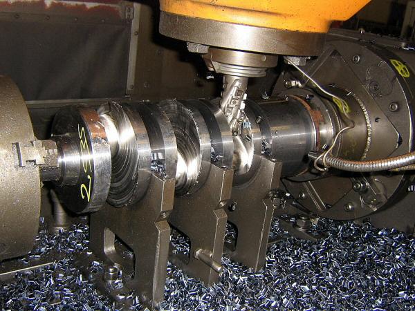
Figure 4: Billet Crankshaft Machining (Courtesy of Bryant Racing)
There is an old argument that a forged crank is superior to a billet crank because of the allegedly uninterrupted grain flow that can be obtained in the forging process. That might be true of some components, but with respect to crankshafts, the argument fails because of the large dislocations in the material that are necessary to move the crankpin and counterweight material from the center of the forging blank to the outer extremes of the part. The resulting grain structure in the typical V8 crank forging exhibits similar fractured grain properties to that of a machined billet. More than one crankshaft manufacturer has told me that there is no way that a forging from the commonly used steel alloy SAE-4340 (AMS-6414) would survive in one of today's Cup engines.
Some years ago, there was an effort at Cosworth to build a Formula One crankshaft by welding together various sections, which comprised the journals, webs and counterweights. The purported intent was to be better able to create exactly the shape and section of the various components, thereby reducing MMOI while achieving the same or better stiffness. While no one was willing to divulge details about the effort, it is rumored to have been run once or twice then abandoned due to the high cost and complexity compared to the measurable benefits.
In certain cases, there are benefits to the use of a built-up crankshaft. Because of the ‘master-rod’ mechanism necessary for the implementation of the radial piston engines that powered most aircraft until well into the second half of the 20th century, a bolted-together crankshaft configuration was used almost exclusively. Figure 5 illustrates a typical two-row composite radial crankshaft and master-rod layout. The loose counterweights will be addressed later in this article.
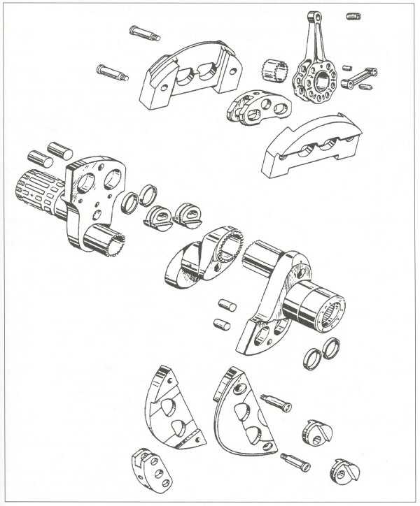
Figure 5: Built-up Radial Engine Crankshaft
CRANKSHAFT MATERIALS
The steel alloys typically used in high strength crankshafts have been selected for what each designer perceives as the most desirable combination of properties. Figure 6 shows the nominal chemistries of the crankshaft alloys discussed here.
Medium-carbon steel alloys are composed of predominantly the element iron, and contain a small percentage of carbon (0.25% to 0.45%, described as "25 to 45 points" of carbon), along with combinations of several alloying elements, the mix of which has been carefully designed in order to produce specific qualities in the target alloy, including hardenability, nitridability, surface and core hardness, ultimate tensile strength, yield strength, endurance limit (fatigue strength), ductility, impact resistance, corrosion resistance, and temper-embrittlement resistance. The alloying elements typically used in these carbon steels are manganese, chromium, molybdenum, nickel, silicon, cobalt, vanadium, and sometimes aluminium and titanium. Each of those elements adds specific properties in a given material. The carbon content is the main determinant of the ultimate strength and hardness to which such an alloy can be heat treated.
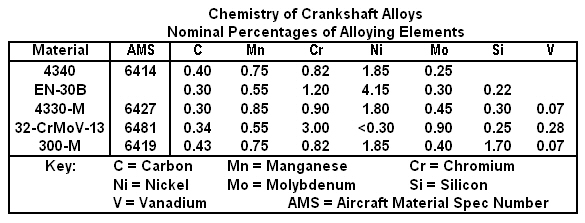
Figure 6: Typical Crankshaft Alloy Chemistries
In addition to alloying elements, high strength steels are carefully refined so as to remove as many of the undesirable impurities as possible (sulfur, phosphorus, calcium, etc.) and to more tightly constrain the tolerances, which define the allowable variations in the percentage of alloying elements. The highest quality steels are usually specified and ordered by reference to their AMS number (Aerospace Material Specification). These specs tightly constrain the chemistry, and the required purity can often only be achieved by melting in a vacuum, then re-melting in a vacuum to further refine the metal. Typical vacuum-processing methods are VIM and VAR.
Vacuum Induction Melting (VIM) is a process for producing very high purity steels by melting the materials by induction heating inside a high-vacuum chamber.
Vacuum Arc Remelting (VAR) is a refining process in which steels are remelted inside a vacuum chamber to reduce the amount of dissolved gasses in the metal. Heating is by means of an electric arc between a consumable electrode and the ingot.
There are other ultra-high-strength steels that are not carbon steels. These steels, known as "maraging" steels, are refined so as to remove as much of the carbon as possible, and develop their extreme strength and fatigue properties as a by-product of the crystalline structures resulting from the large amounts of nickel (15% and up) and cobalt (6% and up) they contain. These steels can achieve extreme levels of strength and maintain excellent levels of impact resistance. As far as I could determine, maraging alloys are not currently (2008) used for racing crankshafts but they have been used in certain extreme application conrods.
In the high performance crankshaft world, the nickel-chrome-moly alloy SAE-4340 (AMS-6414) has been a favorite in both forged and billet applications. It is used because of its very high strength and fatigue properties, coupled with good ductility and impact resistance at high strengths. SAE-4340 contains a nominal 40 points of carbon and is often described as "the standard to which other ultra-high strength alloys are compared".
There is evidence that a lower carbon content provides better impact resistance (reduced notch sensitivity) in certain alloys. The air-hardening nickel-chrome-moly alloy EN-30B is used in some high-end billet crankshafts, in both commercial and VAR forms. This alloy contains 30 points of carbon, and has a nickel content exceeding 4% (400 points). It has good impact resistance at high strengths and is often used in rock-drilling equipment and highly-stressed gears and transmission components. The fact that it can be air-quenched to typical crankshaft core hardness is an added advantage because the distortions and residual stresses which result from oil quenching are avoided. Several manufacturers offer billet crankshafts in EN-30B.
At least one US manufacturer of extreme duty crankshafts for NASCAR Cup, Top Fuel, Pro-Stock, early IRL, and other venues has selected a high-purity, lower-carbon version of the 43xx series of nickel-chrome-moly steels, a high-grade variant of E-4330-M (AMS 6427). This material has a nominal 30 points of carbon and has become a favorite for oil drilling and jet engine components because of its very high toughness and impact resistance when heat-treated to high strengths. This manufacturer uses slight variations in the chemistry for different applications, but was understandably reluctant to discuss the variation specifics and how they affected the desired properties. The company maintains tight control over the entire process by purchasing its specific chemistry materials from a single, extreme-quality steel manufacturer, and by doing its heat-treating, cryogenic processing, ion-nitriding and high-tech inspection all in-house. The use of ion-nitriding allows the nitride process to be done subsequent to finish-grinding.
The material which is currently viewed as the ultra-extreme crankshaft alloy is a steel available from the French manufacturer Aubert & Duval, known as 32-CrMoV-13 or 32CDV13. It is a deep-nitriding alloy containing 300 points of chrome, developed in the mid-nineties specifically for aerospace bearing applications. It is available in three grades. GKH is the commercial purity and chemistry tolerance. GKH-W is the grade having higher purity (VAR) and tighter chemistry tolerance. GKH-YW is the extremely pure grade (VIM - VAR) and is said to cost twice as much per pound as the -W grade.
According to data supplied by Aubert & Duval, fatigue-tests of the -W and -YW grades, using samples of each grade heat treated to similar values of ultimate tensile strength, show consistently that the -YW grade achieves a dramatic improvement (over 22%) in fatigue strength compared to the -W grade, and the endurance limit is claimed to be just a bit short of the yield stress, which is truly amazing. I have been told that, because of the extreme stress levels on Formula One crankshafts, most of them use the -YW grade, while the lower stress levels of a Cup crank allow the successful use of the -W grade.
One well-known manufacturer (Chambon) has developed a process which allows the production of a deep case nitride layer in this alloy (almost 1.0 mm deep, as compared to the more typical 0.10 to 0.15 mm deep layer). They say this deeper case provides a far less sharp hardness gradient from the >60 HRc surface to the 40-45 HRc core, which improves the fatigue and impact properties of the steel. It says that its deep-case process requires several days in the nitriding ovens, but the depth allows finish-grinding after nitriding, using a very sophisticated process to remove the distortions which occurred during the nitriding soak.
No discussion of high-end crankshaft materials would be complete without mention of the ultra-high-strength alloy known as 300-M (AMS 6419). This alloy is a modification to the basic 4340 chemistry, in which a few more points of carbon are added (higher achievable hardness and strength), along with 170 points of silicon and 7 points of vanadium. The vanadium acts as a grain refiner, and the silicon enables the material to be tempered to very high strength (285 ksi) and fatigue properties, while retaining extremely good impact resistance and toughness.
This material (300-M) is expensive and sometimes hard to get, since it is preferred for heavy aircraft landing gear components. It has been used by a few manufacturers for extreme duty crankshafts and conrods as well as high-shock aircraft components. However, several of the manufacturers I spoke with told me that they consider their favorite materials to be much better than 300-M for crankshaft applications. (The reasoning behind this incorrect conclusion is covered on the Engine Materials page).
CRANKSHAFT HEAT TREATING
Regarding the steel alloys typically used in high-grade crankshafts, the desired ultimate (and hence yield and fatigue) strength of the material is produced by a series of processes, known in aggregate as ‘heat treatment’.
The typical heat-treating process for carbon-steel alloys is first to transform the structure of the rough-machined part into the face-centered-cubic austenite crystalline structure (‘austenitize’) by heating the part in an oven until the temperature throughout the part stabilizes in the neighbourhood of 1550°F to 1650°F (depending on the specific material). Next, the part is removed from the heating oven and rapidly cooled ("quenched") to extract heat from the part at a rate sufficient to transform a large percentage of the austenitic structure into fine-grained martensite. The desired martensitic post-quench crystalline structure of the steel is the high-strength, high-hardness, form of the iron-carbon solution. The rate of cooling required to achieve maximum transformation varies with the hardenability of the material, determined by the combination of alloying elements.
Distortion and induced residual stress are two of the biggest problems involved in heat-treating. Less severe quenching methods tend to reduce residual stresses and distortion. Some alloys (EN-30B and certain tool steels, for example) can reach full hardness by quenching in air. Other alloys having less hardenability can be quenched in a bath of 400°F molten salt. Still others require quenching in a polymer-based oil, and the least hardenable alloys need to be quenched in water. The shock of water-quenching is often severe enough to crack the part or induce severe residual stresses and distortions. As the hardenability of a material decreases, the hardness (thus strength) varies more drastically from the surface to the core of the material. High hardenability materials can reach much more homogeneous post-quench hardness.
Cryogenic treatment, if used, directly follows quenching. The body of belief-based and empirical evidence supporting cryo is now supported by scientific data from a recent NASA study confirming that a properly-done cryo process does transform most of the retained austenite to martensite, relaxes the crystalline distortions, and produces helpful η ("eta") particles at the grain boundaries. The resulting material is almost fully martensitic, has reduced residual stress, more homogeneous structure and therefore greater fatigue strength.
After quenching (and cryo if used), the alloy steel material has reached a very high strength and hardness, but at that hardness level, it lacks sufficient ductility and impact resistance for most applications. In order to produce the combination of material properties deemed suitable for a given application, the part is placed in a ‘tempering’ oven and soaked for a specific amount of time at a specific temperature (for that alloy) in order to reduce the hardness to the desired level, hence producing the desired strength, ductility, impact resistance and other desired mechanical properties. In the case of certain alloys, a double-tempering process can further improve fatigue strength and notch toughness. The tempering temperature and time must be carefully determined for each specific steel alloy, because in mid-range temperature bands, martensitic steels exhibit a property known as temper embrittlement, in which the steel, while having high strength, loses a great deal of its toughness and impact resistance.
Typically, the post-temper hardness which results in the best ductility and impact properties is not sufficient for the wear surfaces of the crank journals. In addition, the fatigue strength of the material at that hardness is insufficient for suitable life. The currently- favored process which provides both the hard journal surfaces and dramatic improvements in fatigue life is nitriding (not "nitrating" - nitrates are oxygen-bearing compounds of nitrogen).
Nitriding is the process of diffusing elemental nitrogen into the surface of a steel, producing iron nitrides (FeNx). The result is a hard, high strength case along with residual surface compressive stresses. The part gains a high-strength, high hardness surface with high wear resistance, and greatly improved fatigue performance due to both the high strength of the case and the residual compressive stress. These effects occur without the need for quenching from the nitriding temperature. The case thickness is usually quite thin (0.10 to 0.20 mm), although at least one crankshaft manufacturer has developed a way to achieve nitride layer thickness approaching 1.0 mm.
There are three common nitriding processes: gas nitriding (typically ammonia), molten salt-bath nitriding (cyanide salts) and the more precise plasma-ion nitriding. All three occur at approximately the same temperatures (925 - 1050°F) which, of course, becomes the ultimate tempering temperature of the part. The effectiveness of nitriding varies with the chemistry of the steel alloy. The best results occur when the alloy contains one of more of the nitride-forming elements, including chromium, molybdenum and vanadium.
Older crankshaft technology involved heat-treating to a higher core hardness and shotpeening the fillet radii for fatigue improvement. Figure 7 shows the relative fatigue strength of 4340 material from heat treating alone, heat-treating plus shotpeening, and heat treating plus nitriding.
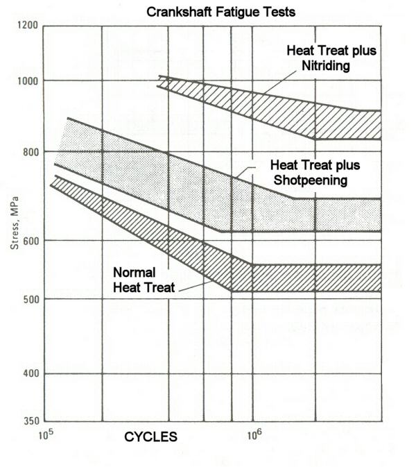
Figure 7: Fatigue Life Improvements
CRANKSHAFT DESIGN ISSUES
In the world of component design, there are competing criteria, which require the engineers to achieve a perceived optimal compromise to satisfy the requirements of their particular efforts. Discussions with various recognized experts in the crankshaft field make it abundantly clear that there is no ‘right’ answer, and opinions about the priorities of design criteria vary considerably. In contemporary racing crankshaft design, the requirements for bending and torsional stiffness (see the Strength vs. Stiffness discussion below) compete with the need for low mass moment of inertia (MMOI). Several crankshaft experts emphasized the fact that exotic metallurgy is no substitute for proper design, and there is certainly no point in switching to exotics if there is no fatigue problem to be solved.
High strength is obviously a benefit in terms of enabling the crankshaft to survive the various stresses which result from (a) the loads applied to the piston / conrod components by the vector resolutions of the ever-varying cylinder pressures and reaction loads which occur during the four (or two) strokes per cycle) and (b) inertia loads resulting from the constantly-varying accelerations and decelerations exerted on the piston / conrod assemblies (see PISTON MOTION)
High stiffness is a benefit because it (a) reduces bending deflection of the bearing journals and webs, and (b) it increases the torsional resonant frequency of the crankshaft. Journal deflection can cause increased friction by disturbing the hydrodynamic film at critical points, and can cause loss of lubrication because of increased leakage through the greater radial clearances that occur when a journal's axis is not parallel to the bearing axis. In extreme cases, it can cause metal-to-metal contact between the journal and the bearing. Increasing the crankshaft torsional resonant frequency might or might not be a benefit, depending on several factors including engine operating range, crankshaft excitation orders, rotating masses, and others
STRENGTH vs. STIFFNESS
The following material is an attempt to explain the apparently-universal misunderstanding of the two different concepts of STRENGTH and STIFFNESS.
Metal parts are not rigid. When a load is applied to a metal part, the part deflects in response to the load. The deflection can be very small (crankshaft, conrod, etc.) or it can be quite large (valvesprings, etc). But to one degree or another, all parts behave like springs in response to a load. The ultimate strength of a material is a measure of the STRESS LEVEL which can be applied to a lab sample of the material before it fractures. The degree to which a given part resists deflection in response to a given loading is called stiffness.
It is important to understand that the ultimate strength of a material has nothing whatever to do with the stiffness {resistance to deflection} of a component. STIFFNESS (or RIGIDITY) is the result of two properties of a part: (1) the Young's Modulus of the material (sometimes called Modulus of Elasticity, but more appropriately named Modulus of Rigidity) and the cross-sectional properties of the part to which the load is applied.
For example, suppose you have two components which are identical in all respects (same material, same dimensions) except the tensile strength to which those components have been heat-treated. If you apply an increasing load to each component, both will deflect the same amount for each load value, until the component with the lower strength permanently deforms (and breaks if it is loaded and constrained in a certain way) at a relatively low stress level. The component with the higher strength will continue to deform with increasing load until its yield stress is reached, at which point it too will permanently deform.
Since the current crankshaft materials are alloy steels, the Young's Modulus is fairly constant. That means that altering the section properties of the highly-stressed portions of the crankshaft is the only way to increase stiffness. Of course, adding material works at cross-purposes to maintaining low MMOI.
Three major parameters which affect crank STIFFNESS are (a) crankshaft length, (b) journal diameter and (c) crankpin overlap (CPO). The torsional stiffness and bending of a cylindrical section (journal) varies directly with length and with the FOURTH power of diameter.
Crankpin overlap is a measurement of how much crankpin material is horizontally aligned with the material of the adjacent main journals, as illustrated in Figure 8, showing a CPO of 0.225 with a 4.250" stroke crank having 2.100 rod journals and 2.600 main journals. CPO has a direct relationship with both the stiffness (torsional and bending) and the peak stress levels in the crankshaft. The calculation for CPO is as follows:
CPO = (main diameter + crankpin diameter - stroke) / 2
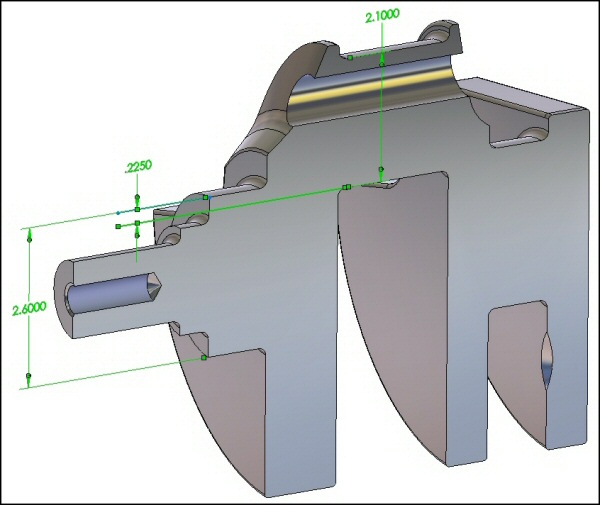
Figure 8: Crankpin Overlap Illustration
Although Figure 8 illustrates what CPO is, it does not fully demonstrate the importance of CPO with regard to crankshaft stiffness (both torsionally and bending) and with regard to bending and shear stresses. The following picture (Figure 9) shows a cross section that better demonstrates the effect of reduced CPO, using dimensions from the contemporary GM "LS" series of engines. The dark (football shaped) segment of each illustration shoes the amount of actual marerial area provided by the three different CPO values.
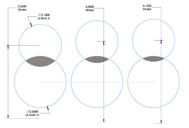
Figure 9: Crankpin Overlap Illustration
All three illustrations use the LS / LT crankpin diameter (2.100") and Main Journal diameter (2.560"). The leftmost diagram shows a section view of the current standard crankshaft configuration, with the 3.622" stroke used in the LS-3, LS-9, LT-1, and LT-4 engines. The center diagram shows the 4.000" stroke used in the LS-7 engines. The right diagram shows the 4.125" stroke used in the LSX-454 engine.
Notice how much smaller the CPO cross sectional area becomes as the CPO dimension decreases. The stroke, CPO and area values ( inches / inches / inches² respectively) are: (3.622" / 0.519" / 0.516 in²); (4.000" / 0.330 in / 0.265 in²); (4.125" / 0.268 " / 0.195 in²). The significant part of that demonstration is the fact that goung from a 3.622 stroke (LS-3, LS-9) to a 4.000 stroke (LS-7) reduces the CPO dimension by 36%, but reduces the cross sectional area by almost 50%. The 4.125 stroke crank area is 62% less than the 3.622 stroke crank.
WEIGHT and MOMENT of INERTIA
There is a continuing emphasis on research and design among F1 and Cup teams to increase stiffness with minimal impact on MMOI. However, all the experts I spoke with were understandably reluctant to discuss the specifics of where and how they are adding material and how effective their changes are. From examining some available pictures and gathering data on other engine parameters, I would hazard a guess that the conrod bearing widths are being reduced to make room for thicker webs. It is also possible that main bearing journals are being undercut to produce the required fillet radii at the intersection with the web, again making more room for thicker webs.
Undercutting the journals increases the stress levels and locally reduces the section properties. However, the immense fatigue strengths of the contemporary materials and the relative lack of crank failure at the highest levels of racing suggest that the endurance limits can be pushed a bit further. It is apparent that a great deal of FEA work is essential at the top.
One area where most two-plane V8 engine people agree is the use of center counterweights. It has been known for some time that, depending on the stroke and engine operating range, there can be power and reliability gains available in V8s that use two-plane crankshafts from the use of counterweights around the center main bearing (Figure 10).
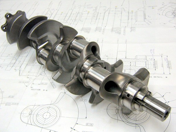
Figure 10: Fully-Counterweighted Two-Plane V8 Crankshaft (Courtesy of Bryant Racing)
Traditionally, many two-plane V8 crankshafts had been produced without center counterweights because of economies and difficulties forging the blanks, because the six-counterweight crank typically has a slightly lower MMOI, and because the benefits of an eight-counterweight crank in a short-stroke application were not fully appreciated.
However, the bending deflection across the center main at high loadings and high speeds causes measurable losses, so many areas of racing which use two-plane V8 cranks are moving (or have already moved) to eight-counterweight cranks. rom an overall engine design perspective, the relocation of the thrust bearing from the rear main to the center main also helps reduce center-main bending deflection.
There are varying opinions about whether high stiffness or low MMOI is more important. Low MMOI is most important at high engine acceleration rates. Road-course racing typically involves greater vehicle speed variation per lap, which implies greater requirements for quick acceleration through several gear ratios. In certain classes, the low weight of the vehicle and the high power of the engine can yield very high engine acceleration rates. At the higher-speed Cup racing circuits, the engine acceleration rates at speed are often less than 100 RPM per second, while at some of the shorter tracks, they can exceed 500 RPM per second. Of course, there are restarts and pit stops to be dealt with at all tracks, so it is easy to see how there can be varying approaches to this issue.
Reducing MMOI involves removing material, especially from places which are a long distance from the main bearing axis. However, these are also some of the most highly loaded areas as well, so reducing cross sectional properties necessarily increases the cyclic stress levels. Pushing the cyclic stress levels up impinges on the fatigue life of the component, which is especially important in classes where an engine must, by regulation, survive more than one meeting. Determining acceptable levels of cyclic stresses vs. expected life is more an empirical than an exact science. Endurance limit testing of materials produces a highly statistical array of results data (as illustrated in Figure 7).
There has been quite a bit of discussion about the use of bolt-on counterweights in an attempt to reduce MMOI values. An example of this technology is shown in Figure 11. These detachable counterweights are made from variants of the ‘heavy metal’ used to balance crankshafts. This heavy metal is a tungsten-based alloy with several different chemistries (W-Ni-Cu; W-Ni-Fe; W-Ni-C) depending on the required properties. These alloys have nearly 2.5 times the density of steel, and are extremely expensive.
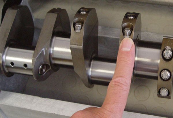
Figure 11: Bolt-On Counterweights
Another benefit of bolt-on counterweights is that several of the machining operations are much simpler to accomplish without having to deal with the integral counterweights getting in the way. If journal coatings are used, the more complete access to the journals provided by the absence of integral counterweights could also be a benefit.
There were some initial problems with bolt-on counterweights, which resulted (as one Formula One designer told me) in "several deep holes being dug in the surface of a few racetracks". There are tensile and fatigue stress issues, as well as the inevitable fretting between contact surfaces and the requirement for highly developed fastener technology. Usage in Formula One suggests that those issues have been resolved. There is a variance of opinion as to whether bolt on counterweights are being investigated in Cup. One person told me they are explicitly illegal, while two others told me they know of a certain amount of investigation and development going on in that regard.
In the world of two-plane V8 cranks, the traditional calculation for the balance-bobweight value is 100% of the rotating weight (big end, inserts and oil) plus 50% of the reciprocating weight (small end, wristpin, retainers, piston, rings and oil). However, there are differing approaches to the question of overbalance or underbalance. Some experts stick with the 100% + 50% distribution, while others opt for a 46-47% underbalance (100% + 47%). Others prefer a 52-53% overbalance, while others add an arbitrary 100 grams to the 50% reciprocating calculation. There was a general reluctance among the crankshaft experts with whom I spoke to discuss the expected or observed effects of these strategies.
LUBRICATION
There has been an interesting development regarding two-plane V8 crankshaft lubrication drillings. Traditionally, each rod bearing was fed oil by a single angled hole from the loaded-during-compression side of the rod journal to the less-loaded side of the adjacent main journal, sometimes called ‘straight-shot oiling’, shown in Figure 12. That strategy reduced the effect of centrifugal-force starvation at high RPM and assured the availability of sufficient oil to provide the dynamic film strength for the combustion loading.

Figure 12: "Straight-Shot" Oiling
The problem with this scheme is that the intersection of the angled hole with the rod journal produces a large elliptical interruption in the journal surface. Add the chamfering usually done around that hole, and what results is a significant interruption of the hydrodynamic surface area. Coupled with the reduced bearing widths, that divot creates a substantial leakage path for the oil to escape.
The new approach rearranges the drillings so the holes in the rod journal can be perpendicular to the surface. One method is to drill a perpendicular oil hole into the rod journal, and drill an intersecting parallel hole partially through the rod journal and plug the open end. Next, an angled drilling from an adjacent main journal is made to intersect the parallel drilling. Another method involves horizontal drillings through the main journal, through the CPO into the rod journal, with perpendicular feeds into both journals. This rearrangement enables the lubrication of both rods on the same crankpin from a single main journal. That can be an advantage in view of data showing that two-plane V8 main journals numbers two and four are the most highly loaded, so the rods can be oiled from one, three and five while the oil delivered to mains two and four can do a better job because of reduced leakage and no surface interruptions. Figures 10 and 11 show examples of this approach.
An interesting byproduct of this new drilling strategy is the creation of internal sharp corners and edges where the drillings intersect. These sharp corners introduce the flow-restricting effect of sharp-edged orifices into the lube system at a critical point. Further, sharp corners and machining marks introduce stress concentrations due to of the surface discontinuities.
One major crank manufacturer (Bryant Racing) has developed a proprietary extrude-honing system in which an abrasive slurry is pumped through these drillings at high pressure. This abrasive treatment removes the sharp edges and surface flaws which cause flow restrictions and stress concentrations, leaving the inside surfaces of the holes with a mirror finish and nicely rounded intersections, which adds substantially to the fatigue life of the part.
