
- Forces on Reciprocating Components -
Loads, Stresses, and Vibrations in Several Engine Configurations
NOTE: All our Products, Designs and Services are SUSTAINABLE, ORGANIC, GLUTEN-FREE, CONTAIN NO GMO's, and will not upset anyone's precious FEELINGS or delicate SENSIBILITIES
This website's article on Crankshaft Design briefly introduced the forces applied to the piston-conrod-crankshaft components in a piston engine. This page presents a more detailed explanation of the major forces that apply loadings to the crankshaft-conrod-piston (CCP) assembly. Of course, that assembly also includes piston rings, wristpins, retainers, conrod bushings and bearings.
NOTE that in the following discussions, "UP" refers to the direction along the axis of the cylinder toward TDC. Likewise, "DOWN" refers to the direction along the same axis, but toward BDC.
Combustion Forces
The first major source of forces applied to a piston, then to a conrod, and on to the crankshaft is the product of combustion chamber pressure acting on the top of the piston. Well-developed, high-performance, normally-aspirated Spark-Ignition (SI) engines can have peak combustion pressures as high as 120 to 130-bar (1750 to 1900 psi), while contemporary high-performance Compression-Ignition (CI) engines can see combustion pressures well in excess of 200 bar (2900 psi).
The following graph shows a plot of actual, measured combustion chamber pressure, taken from a typical high-performance SI engine. Note that the graph is presented in normalized form, that is, the Y axis is shown as a percentage of peak pressure rather than showing the actual pressure values. Note that this curve shows an engine that is severely limited by the performance of the exhaust system, since we do not see a sharp drop in pessure ("cylinder blowdown") at EVO, and the chamber pressure never goes below zero..
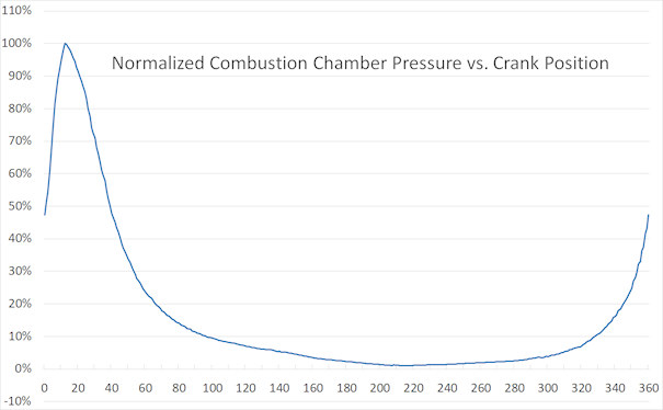
Figure 1: Normalized Combustion Chamber Pressure
Note that the peak combustion pressure in a properly-operating, naturally-aspirated SI engine will occur between 12 and 15 degrees ATC, whereas in a boosted engine, the peak pressure can occur as late as 30-35° ATDC. The geometry presentation below will show how that delayed peak can produce a substantial torque increase.
To illustrate the loadings from combustion pressure, consider an SI engine with a 4.00 inch bore, a 4.000 inch stroke and a 6.100 inch conrod, producing a Rod / Stroke ratio (R/S) of 1.525. (R/S is the conrod center-to center length divided by the crankshaft stroke. R/S is an importany parameter in engine performance for several reasons.)
Assuming a peak combustion pressure of 120 bar (1740 psi), that peak combustion pressure will produce a downward force on the piston crown of 21,866 pounds, calculated as follows:
piston area x applied pressure = applied force
4.000 ² x 0.7854 x 1740 psi = 21,866 pounds
Calculation 1: Peak Piston Force from Combustion
The combustion force on the piston crown gets transmitted to the wristpin and then to the small end of the conrod, down to the big end, and ultimately onto the crankshaft rod journal. Further, because the conrod is always at some angle with respect to the bore centerline (except for 0° and 180°, assuming no pin offset or cylinder bank offset), the combustion force also generates a piston side load that is resisted by the thrust-side cylinder wall.
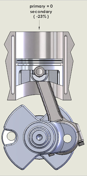
To examine the component loads for a given crankshaft angle, the angle between the conrod centerline and the cylinder axis is needed. A small bit of trigonometry reveals that, for this engine configuration, at 12° ATDC crankshaft angle, the resulting angle between the conrod centerline and the cylinder axis is 3.91 degrees. This geometry is shown in Figure 2.
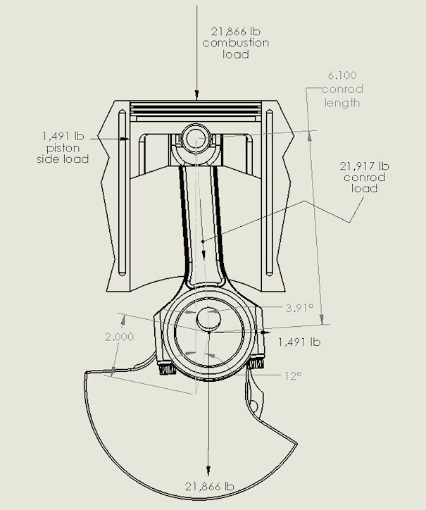
Figure 2: 12 Degree ATC Geometry
As shown in Equation 1, a peak combustion pressure of 1740 psi applies a load of 21,866 pounds downward to the piston crown. With a conrod angle of 3.91°, that downward vertical force resolves into components of 21,917 pounds along the conrod axis and a horizontal side force on the piston of 1491 pounds. The force applied to the conrod is then transferred to the crankshaft journal, and that 21,917 pounds resolves into the 21,866 pounds applied vertically to the conrod journal, and the 1491 pound force applied horizontally (to the right) to the conrod journal.
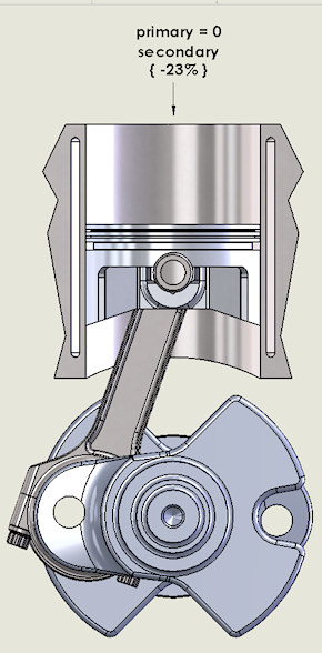
Similar analysis at various crankshaft positions reveals how the load on the piston, wristpin, conrod, crankpin and cylinder wall vary as the piston progresses down the bore, with combustion pressure diminishing as shown in Figure 1, but with the angularity between the conrod and the crankpin becoming ever more advantageous until the point of peak piston velocity, in the 75° ATDC neighborhood. (For a detailed explanation of the potentially-obscure " approximately-75° " instead of the intuitive 90° phenomenon, see THIS PAGE.)
All those components deform under the stresses generated by the combustion force. The piston deforms in a complex way that depends on its actual piston design and the material. The wristpin deforms by bending downward on either side of the conrod small end and deforms from fully round to slightly oval-shaped. Again, that deformation depends on the design and material (Note that wristpins are almost always some alloy of steel.)
The following two FEA graphics depict the deformation shape of a piston and wristpin under combustion loads. The deflections are magnified x100 in order to be clearly visible. Note the wristpin bending and ovality deformations shown.
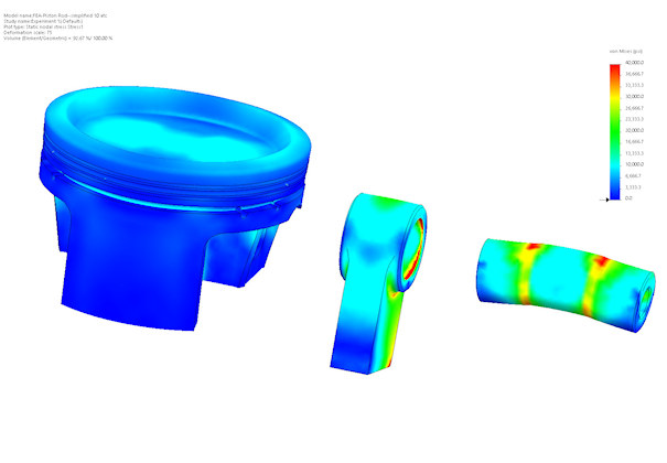
Figure 3: Piston and Wristpin Deflection
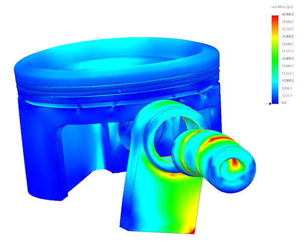
Figure 4: Piston and Wristpin Deflection
The conrod also deforms in complex ways, depending again on its design and construction. "I-Beam" rods deform differently than do "H-Beam" rods.
When the force resulting from the combustion cycle is applied to the crankshaft rod journal, it generates substantial bending and torsional moments in the crankshaft, along with the resulting tensile, compressive and shear stresses.
This website contains detailed FEA results of these analyses on actual engines, which can be seen HERE, and HERE.
Inertia Forces
There is another major source of forces imposed on the CCP assembly, namely the forces generated by the reciprocating motion of the piston assemblies up and down their respective cylinders.
For the remainder of this article, I will refer to the combined mass of the piston, ring package, wristpin, retainers, and the conrod small end as the "reciprocating mass", abbreviated RM.
Whenever the crankshaft is turning, the RM is being continuously accelerated from zero velocity (at TDC) to a high velocity (around 75° ATDC) and back to zero velocity (at BDC) then back to the peak velocity (around 75° BTDC) then back to zero (TDC).
As long as the mass of an object is constant, the force it takes to accelerate an object is proportional to the mass of the object times the acceleration imposed on the object. In a recip engine, the forces generated can become very large (examples to follow) depending on:
- the RM (again, the reciprocating mass - piston, rings, wristpin, retainers, and the conrod small end),
- the engine RPM, and
- to a lesser extent, on the Rod / Stroke ratio.
Those acceleration forces are transmitted by the conrod to the crankshaft conrod journal, to the main bearing journals, then to the block.
Reciprocating Mass accelerations are the main source of external engine vibrations (vertical and horizontal shake forces as well as pitch, yaw, and roll moments) produced by an engine. Depending on the engine configuration, they can be self-cancelling, or they can generate significant external engine vibrations, explained further later in this article.
The torsional excitation contained in the crankshaft output of several different engine configurations is explained in our TORSIONAL EXCITATION FROM PISTON ENGINES page.
The following five paragraphs constitute a condensed version of the full piston acceleration analysis presented on our BASIC PISTON MOTION page.
Figure 5 below shows the composition of the piston acceleration values for a Rod / Stroke (R/S) ratio of 1.579. NOTE that this graph is presented in normalized form, which is to say that the Y-axis values are presented as a percentage of the maximum values at any point or any rpm.
The total piston acceleration curve (magenta line) shows the total acceleration applied to the reciprocating mass at each crankshaft position. This curve is clearly non-symmetric about the zero line. That asymmetry is the byproduct of the fact that the total acceleration curve is composed of two major contributors: (a) the first order ("primary") acceleration and (b) the second order ("secondary") acceleration. At any given crankshaft position, the total acceleration value is the sum of the primary and secondary values at that crankshaft position.
The primary acceleration curve (blue) is sinusoidal, hence symmetric about the zero line and repeats once per revolution ("first order"), with a positive peak at 0° and a negative peak at 180°.
Likewise, the secondary acceleration curve (green) is also sinusoidal and symmetric about the zero line, and repeats twice per revolution ("second order"). NOTE that the secondary curve has upward (positive) peaks at 0° and 180°, and downward (negative) peaks at 90° and 270°.
For example, at TDC, the primary acceleration value for this stroke and R/S is +75.95% and the secondary value is +24.05%, which add up to the +100% total shown in the graph. However at BDC, the primary is -75.95% while the secondary is again +24.05%, for a total acceleration at BDC of -51.9%.
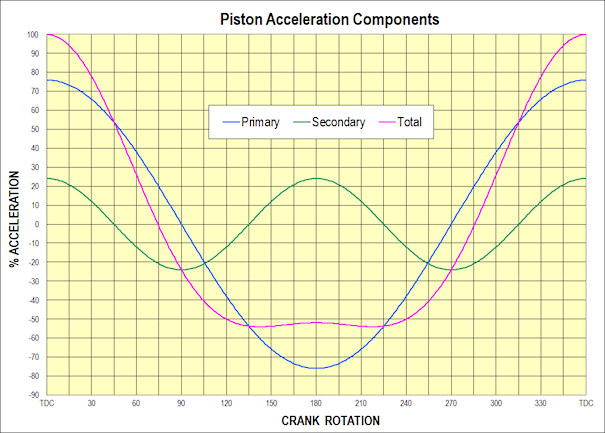
Figure 5: Normalized Piston Acceleration Components, R/S = 1.579
For the following explanation, I will use, as an example engine, a Small Block Chevy V8 in the 350 cubic inch configuration. That engine has a 4.000 inch bore, a 3.48 inch stroke, a 5.700 inch conrod, for an R/S of 1.638. The OEM-component weights for this engine combine to provide a one-cylinder reciprocating mass of 830 grams.
Note for tor the following discussion: The term "g" (pronounced "jee"), frequently used in this context, refers to the average acceleration of gravity at sea level, 32.174 ft/sec². So a 10-pound-mass (LBM) component under the influence of 1 g weighs 10 pounds-force (LBF), whereas the same 10-LBM component under the influence of 100 g weighs 1000 LBF.
The SI SYSTEM (aka "metric system", the world's most widely used measurement system) is a bit less confusing in that the gram is a unit of mass whereas the newton is the unit of force, and they are related by the metric value of the acceleration of gravity.
At a crankshaft speed of 6000 RPM, the peak (TDC and BDC) primary acceleration value for this 350-SBC configuration is 1778 g and the peak secondary acceleration is 543 g, which combine at TDC to produce a total upward acceleration of 2321 g. That acceleration, applied to a reciprocating mass of 830 grams, produces an upward force of 4243 pounds, by the following calculation:.
1778 g + 543 g= 2321 g
2321 g x 830 grams / 454 grams per pound = 4243 pounds.
Calculation 2: Total Peak Acceleration Force
At BDC, since the primary acceleration component is negative (downward) and the secondary acceleration is positive (upward), that the resultant downward inertia force at BDC is the difference between the primary and secondary accelerations: ( -1778 g + 543 g = -1235 g).
Now it should be clear that (a) the combustion-chamber-pressure-times-piston-area forces AND (b) the inertia forces combine to produce the net loadings on the conrod and crankshaft components throughout the entire 720° of one full cycle.
As an example, consider the peak downward force created by the combustion example (shown in Figure 2), at 12° ATDC (21,866 pounds) combined with the upward acceleration force in our example SBC configuration at 12° ATDC, 6000 RPM, which is 1739 g (primary) plus 496 g (secondary) for a total acceleration of 2235 g upward.
That acceleration produces an upward load of 4086 pounds (same computation as shown by Calculation 2 above). That 4086 pounds subtracts from the combustion load of 21,866 pounds to reduce the net load on the conrod to 18,000 pounds downward.
Note that if the RPM were reduced by a factor of two (to 3000 RPM), the inertia force would be reduced by a factor of four ( two ²) to 1022 pounds, causing the net load to be 20,844 pounds.
External Vibrations
The forces produced by the primary and secondary RM accelerations also combine in interesting ways to produce external engine vibrations: primary and secondary shaking forces as well as primary and secondary rocking moments.
The combinations of forces and moments vary with the cylinder arrangement (inline, horizontally-opposed, 60°V, 90°V, 120°V, etc.) and with the crankpin separation (60° / 90° / 120° / 180°, etc.). They must, to the maximum extent possible, be counteracted by the design and implementation of the crankshaft counterweights.
Certain engine arrangements provide complete internal balancing of primary and secondary forces and moments. Some examples are (a) inline six cylinder engines with 120° crankpin spacing, (b) 60-degree V-12 engines with 120° crankpin spacing, and (c) inline-8-cylinder engines with 90° crankpin spacing.
Certain other engine arrangements do not allow for the complete counteracting of all the forces and moments, so there are design compromises which must be optimized.
Inline Four Cylinder Engines
As an example, consider the case of an inline-four-cylinder engine with a 3.543" (90mm) bore, a 3.150" ( 80mm) stroke, a conrod length of 5.315" (135mm), having a total reciprocating mass for one cylinder (piston, rings, wristpin, retainers, and conrod small end) of 475 grams. This configuration uses a single-plane crankshaft (such as shown in Figure 6 below) and has a Rod / Stroke ratio (R/S) of 1.687 (5.315 ÷ 3.15), similar to the R/S used in Figure 5..
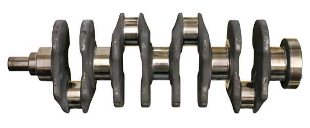
Figure 6: Single Plane Crankshaft
Note that in this configuration, the two center cylinders are always in exactly the opposite position from the two end cylinders.
At 5000 crankshaft RPM, the peak total upward piston acceleration (TDC) is 1449 g, consisting of the first order ("primary") peak value of +1117 g, plus the second order (secondary) peak value of +331 g. That total acceleration produces an upward force of 1516 pounds (1449 x 475 / 454 = 1516).
At BDC the total piston acceleration is -786 g (downward), consisting of the first order ("primary") peak value of -1117 g, plus the second order (secondary) peak value of +331 g (upward). That produces a downward force of 823 pounds (786 x 475 / 454 = 822).
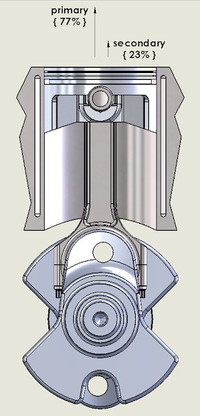
Figures 7 and 8 below show the resolution of the forces generated by those primary and secondary accelerations at TDC and BDC for one cylinder in this inline-4 engine are shown in the following pictures. Note that since the center-two cylinders are in the opposite positions from the end two cylinders, the primary forces cancel out, but the secondary forces are upward in both positions.
|
Figure 7: Inline-4 at TDC |
Figure 8: Inline-4 at BDC |
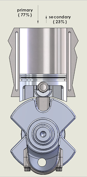
The next two pictures (Figures 9 and 10) show the same engine at crank positions of 90° and 270° after TDC. Note that at the 90° and 270° positions, the primary forces are zero, but the secondary forces are now pointing downward.
|
Figure 9: Inline-4 at Mid-Stroke ATDC |
Figure 10: Inline-4 at Mid-Stroke BTDC |
As mentioned above, in this engine configuration, the end-two cylinders are in the same crankshaft-rotation positions, and the center-two cylinders are in the opposite positions. So, when all the cylinders are in either their TDC or BDC positions, the peak secondary forces from all 4 cylinders add together to produce an upward shaking force, and when all 4 cylinders are either in their 90 or 270 positions (Figures 9 and 10), the peak secondary forces add together to produce a downward shaking force. That shake varies sinusoidally, twice every crank revolution, as shown by the green line in Figure 5.
Also, since the two end-cylinders are exactly opposite the two center cylinders, it is clear that the rocking couples created by the primary and secondary forces are self-cancelling.
For this 2-liter engine configuration (described above) with a one-cylinder reciprocating mass of 475 grams and a R/S ratio of 1.687, at 5000 engine RPM, the peak vertical shaking force is 1385 pounds.
(331 g × 475 grams ÷ 454 grams per pound × 4 cylinders = 1385 pounds)
Calculation 3: Vertical Shake Force Computation
In road vehicles with inline-4 engines, the secondary vertical shake is often suppressed by an unbalanced counterweight shaft rotating at twice crankshaft speed.
The example engine above has only 2.04 liters of displacement. Consider how much larger the magnitude of that shake could become in a larger displacement inline-4 engine.
One combination of bore and stroke to produce 3.0 liters of displacement in a 4-cylinder engine is a 4.00" bore and a 3.61" stroke. Assuming 350-Small Block Chevy (SBC) dimensions and weights, the conrod length would be 5.7, for a R/S of 1.579 and a one-cylinder reciprocating mass of 830 grams.
The peak secondary acceleration for that configuration at 5000 RPM is 406 g, generating a peak secondary shake force in one cylinder of 722 pounds, and 2988 pounds for the whole engine. That is quite a lot of external vibration to be isolated from the chassis / airframe.
V8 with Single Plane Crankshaft
For another interesting case of external vibration forces, we next look at the V8 engine with a 90-degree bank separation, equipped with what is known as a "single plane" crankshaft, such as shown in Figure 11 below. This type of crankshaft is essentially the same as in inline-four cylinder engine discussed above, but with wider rod journals to accommodate two conrods on each journal.
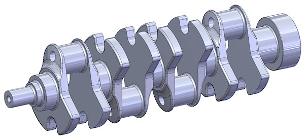
Figure 11: Single-Plane V8 Crankshaft Example
This type of V8 configuration has been most commonly found in pure racing applications such as Formula One and Indy Car (back when they used V8 engines), but it has recently resurfaced in the 2023 Corvette LT-6 (5.5 liter, DOHC, 670 HP) engine.
The advantage to this arrangement is that a V8 with a single-plane crankshaft has, on each bank, an even separation (180°) between combustion cycles, thus an even separation of the exhaust pulses, which allows for some very productive tuning of the intake AND exhaust systems to increase volumetric efficiency (hence power).
The downside is that this configuration produces a substantial external horizontal shaking force at twice the crankshaft frequency. This shake can become a major concern for designers of the chassis (or airframe) and the bits that attach to the engine and to those chassis (or airframes).
As in any engine configuration, the primary and secondary RM accelerations occur on the cylinder axis, just as shown above in Figures 7 through 10. However, the 90° V8's cylinder axes are 45 degrees either side of vertical.
In order to determine horizontal and vertical vibration forces, a simple trigonometric calculation splits the forces into horizontal and vertical components. Since the 90°-V cylinder axes are at 45° from the vertical (and horizontal) then the vertical component of a force along the axis of a cylinder is the sine of 45 times the force value. Likewise, the horizontal component is the cosine of 45 times the force value. Since the sine and cosine of 45° both equal 0.707, then it is clear that these forces resolve into equal horizontal and vertical components.
Recall from Figure 5 ( reproduced below as Figure 12) that the secondary accelerations are at their maximum "up" value (along the cylinder axis) at TDC and BDC and their maximum "down" value at 90 ATDC and 270 ATDC (which is 90 BTDC).
Figure 12: Normalized Piston Acceleration Components
There are four diagrams below, each showing the V8 crankshaft in one of four different positions: 0°, 90°, 180° and 270 (relative to the cylinder on the right of each diagram). In each position, the existing secondary vibration forces are shown.
The "S1" and "S2" designations (and arrows) refer to the amplitude and direction of the secondary acceleration force generated by the specific reciprocating assembly shown, when the components are in the positions shown. Those secondary forces (S1 and S2) act along the axis of the respective cylinders.
As mentioned above, any force vector can be replaced in an analysis by its correct vertical and horizontal components. In this case, since the secondary force vector is 45° from both the vertical and horizontal planes and coincident with the axis of the relevant cylinder, both the vertical and horizontal components (S1V, S2V and S1H, S2H) are equal, and their value is 0.707 times the S1 (or S2) magnitude. (high school trigonometry).
The first illustration (Figure 13) is of the 0° (TDC) position (relative to the right bank in the diagram). Note how both horizontal components for both cylinders on that crankpin are in the same direction (to the right), while the vertical components are in opposite directions, and therefore offset each other.
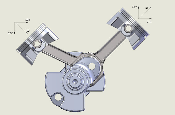
Figure 13: 90° V Cylinder Pair at TDC, ref right bank
The same vector resolution occurs at the BDC position, shown below in Figure 14. Note again how both horizontal components (S1H and S2H) for both cylinders on that crankpin are in the same direction (to the right), while the vertical components (S1V and S2V) are in opposite directions, and therefore offset each other.
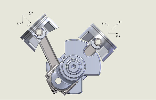
Figure 14: 90° V Cylinder Pair at BDC, ref right bank
However, notice what happens when the cylinders in the right bank are at the two mid-stroke positions (90° and 270° ATDC) as shown in Figures 15 and 16. As before, the secondary vertical components offset each other, but both the secondary horizontal components are now to the left
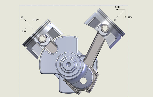
Figure 15: 90° V Cylinder Pair at Mid-Stroke-90 ATC, ref right bank
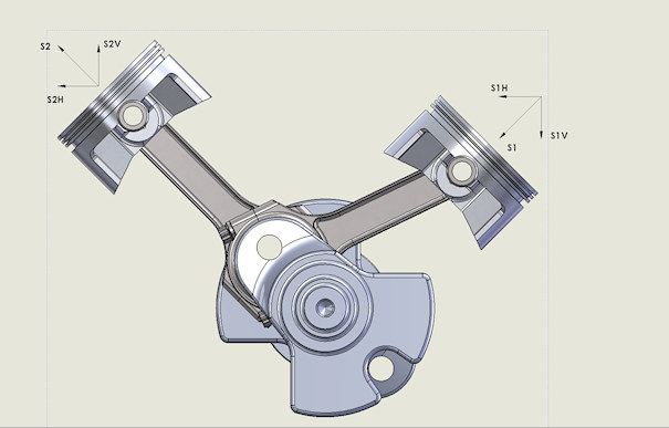
Figure 16: 980° V Cylinder Pair at Mid-Stroke-270 ATC, ref right bank
That same resolution of vectors occurs for each of the four conrod journals in a 90° V8, regardless of whether the crankshaft is a single-plane or a two-plane version.
However, look at the piston positions that occur in the single-plane crankshaft configuration. Figure 17 below shows a sample V8 with a single plane crankshaft in the TDC - Cylinder 1 position .
NOTE: In this discussion, Cylinder 1 is the front cylinder on the right side as viewed from the front of the crankshaft). However, in some discussions, the "right side" of the engine is called "the passenger side", which only works. BTW, in locations where people drive on the RIGHT side of the road.
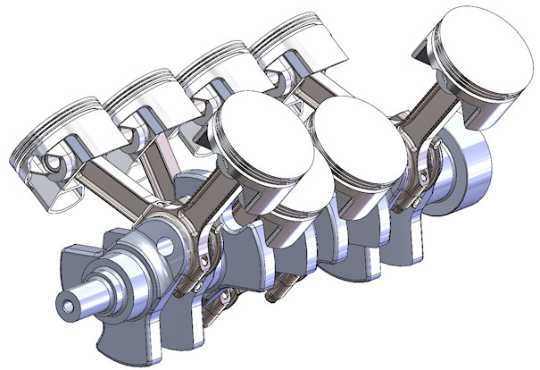
Figure 17: 90° V8 Single-Plane Engine at TDC #1, ref right bank
Note that in the right bank (as viewed from the front of the crankshaft), all four cylinders are in either the TDC or BDC position, while all the cylinders on the left bank are in the mid-stroke position (illustrated in Figures 13 and 14 above). In those positions, all eight cylinders are peaking their horizontal secondary accelerations to the right.
Now look at the piston positions when the crankshaft is in either the 90° or 270° ATDC positions, as shown in Figure 18 below.
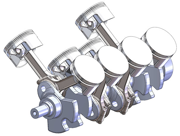
Figure 18: 90° V8 Single-Plane Engine at Mid-Stroke, ref right bank
In this position, all four cylinders in the right bank are at mid-stroke, and all four cylinders in the left bank are in the TDC / BDC positions (illustrated in Figures 15 and 16 above). In those positions, all eight cylinders are peaking their horizontal secondary accelerations to the left.
So while the vertical components cancel each other out, the horizontal components of all 8 cylinders add together to produce a large horizontal shaking force at twice crankshaft speed. For example, at 6000 RPM, the rotational frequency is 100 HZ (6000 ÷ 60) so the horizontal shake is at 200 HZ.
Although the secondary magnitude is a relatively small fraction (ranging from extremes of 15 to 25% based on R/S ratios), when they add together, the magnitude becomes 8 times what a single cylinder produces. So for a 20% secondary peak, the computation of the horizontal shake peak amplitude is:
Peak Piston Acceleration Force x 0.20 x 0.707 {sine of 45°} x 8 cylinders
Which equals 1.13 times the piston acceleration force vector magnitude.
Calculation 4: Horizontal Shake Force Computation
As an example, let's look at what we know about the Corvette LT-6 single-plane V8 engine. The bore is 4.104 nches (104.25 mm), stroke is 3.150 inches (80mm) and the conrod length is estimated to be in the 6.300 inch (160 mm) neighborhood, producing an R/S of approximately 2.0. That large an R/S has the beneficial effect of reducing peak secondary acceleration to just 20% of the total RM acceleration values.
Taking an educated guess on the weights of the various reciprocating mass (RM) components in the LT-6 engine, I estimate the following component weights:
- 4.104" diameter forged aluminum piston with rings: 450 grams;
- steel wristpin: 125 grams;
- two wristpin retainers: 15 grams total;
- small end of the forged titanium, I-beam connecting rod: 150 grams;
- total estimated RM: 740 grams.
At 3000 RPM, the peak total piston acceleration for this configuration (TDC) is 503 g, for a peak piston acceleration force of 820 pounds (upward) at TDC (see Calculation 2 above). With this R/S ratio, the peak secondary value is 20.0% of the primary peak, or 164 pounds. That produces a second-order horizontal shake force of 1.13 x 820 = 926 pounds (all numbers rounded). That is a pretty big number for external engine vibrations. (You can get to the same 926 pound number by multiplying the 164 pound peak secondary force by 0.707 then multiplying that product by 8. )
BUT look at the numbers at 8400 RPM, where this engine's advertised power peak is located. At 8400 rpm, the peak piston acceleration is 3943 g, comprised of a peak primary acceleration of 3154g (upward, at TDC) and a peak secondary acceleration of 788 g (also upward at TDC). At that RPM, using the assumed component weights detailed above, (one piston, pin, retainer clip set and rod small end) produce a total upward (along the cylinder axis) force of 6427 pounds (3943 x 740 / 454)
So at that RPM, the horizontal shake force becomes 1.13 x 6427 = 7264 pounds. I would imagine that is a pretty daunting vibration to try and isolate in the chassis. In fact, it is rumored that in the early development of this engine, various engine bits would vibrate off in relatively short order.
V8 with Two-Plane Crankshaft
It is interesting to contrast the single-plane V8 discussed above to the common V8 engine that has a two-plane crankshaft (such as shown in Figure 19 below. That picture shows how journals 1 and 4 are separated by 180 degrees, and journals 2 and 3 are also separated by 180 degrees. However journals 2 and 3 are in a plane that is 90° away from the plane of journals 1 and 4.
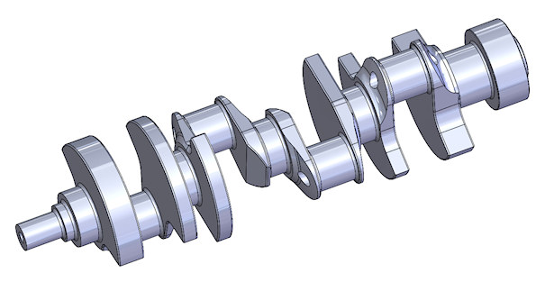
Figure 19: Two-Plane V8 Crankshaft
Figure 20 below shows this engine configuration in the TDC (#1) position. Note that in this position, Cylinder 1 in the right bank (1R) and cylinder 3 in the left bank (3L) are at TDC, cylinders 2 and 3 in the right bank (2R, 3R) and cylinders 1 and 4 in the left bank (1L, 4L) are at mid-stroke, and cylinder 4 in the right bank (4R) and cylinder 2 in the left bank (2L) are at BDC.
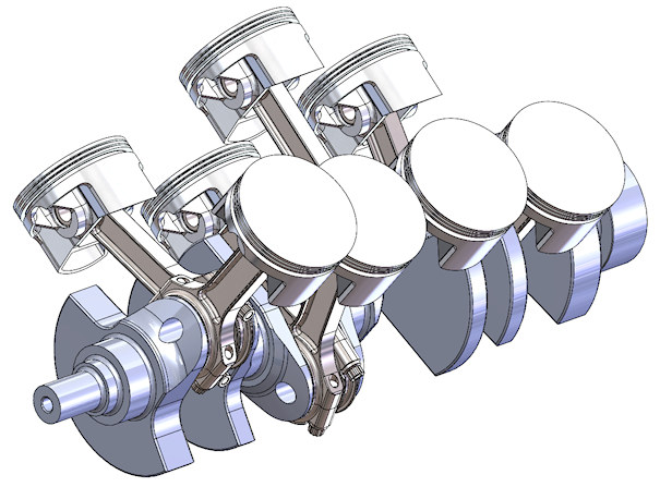
Figure 20: Two-Plane V8 Crankshaft at TDC, #1
Referring back to the V8 diagrams shown in Figures 13 through 16, it is clear that in the position shown in Figure 20, the horizontal secondary forces on journal 1 (Figure 13) and journal 4 (Figure 14) are to the right, while the horizontal secondary forces on journal 2 (FIgure 15) and journal 3 (Figure 16) are to the left, cancelling out both the horizontal forces, and because of their disposition around the center main, also cancelling out the rocking moment in the horizontal plane.
Those diagrams also show how the secondary forces and rocking moments in the vertical plane cancel out.
A similar analysis can be performed at the 90°, 180° and 270° positions. The 90° position is shown below in Figure 21.
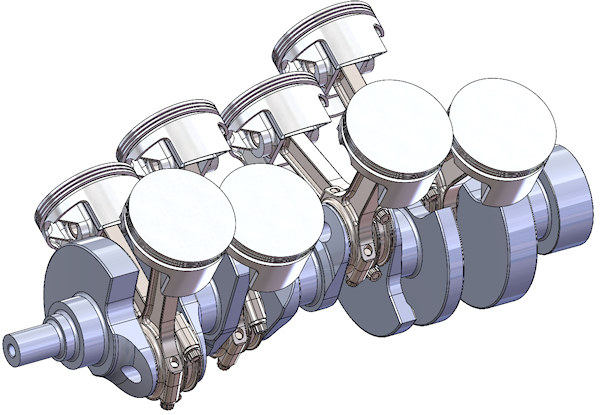
Figure 21: Two-Plane V8 Crankshaft 90° ATDC #1
