Part 9: Cooling System
Design and Features
NOTE: All our Products, Designs, and Services are SUSTAINABLE, ORGANIC, GLUTEN-FREE, CONTAIN NO GMO's, and will not upset anyone's precious FEELINGS or delicate SENSIBILITIES.
NOTE: EPI no longer has any involvement in this engine project. Project delays have occurred for a variety of reasons, resulting in conflict between EPI and the client. As a result, the Client-Contractor relationship has been severed by mutual agreement.
I am leaving these pages on the EPI website to describe the engine design details and technology for the general interest of our many readers.
I paid a great deal of attention to the engine cooling system because of the heat rejection required by the high anticipated peak power outputs and the high sustained power outputs expected in cruise conditions at high altitudes (very low-density cooling air).
The resulting cooling system design incorporates ideas from the Ford FR9, Dodge R6P8, and Chevrolet R-07 NASCAR engines.
Engine heat is typically rejected by four major paths: exhaust, coolant, oil and surrounding ambient air. Contemporary studies of NASCAR Cup engines show that the heat rejection to the coolant and oil has been optimised to about 17% and 4% respectively of the brake power produced. However, that efficiency relies on some sophisticated heat rejection / retention mechanisms.
In NASCAR Cup engines, the use of extremely high coolant and oil temperatures (upwards of 270 F and 325 F respectively) increases the effectiveness of the heat transfer from the heat exchangers to the ambient air (higher delta-T). That reduces the cooling airflow requirement, which in turn reduces the aerodynamic drag of the vehicle, so critical in Cup competition. However those extreme temperatures, coupled with cooling system pressures often approaching 100 psi, reduce the effectiveness of heat transfer from the hot engine parts (lower delta-T), which causes all the hot parts to run much hotter but with an attendant reduction in reliability.
Clearly, vehicle drag is also important to race aircraft, so the use of high coolant and oil temperatures will be investigated during testing of the race version of the engine. However, the other two versions will rely on lower coolant and oil temperatures (180° and 230°F respectively) in the interest of reliability.
If the race version of our V12 can produce 1800 bhp, then a conservative estimate of the heat rejected into the cooling system is 407 hp (22%), which converts to 17,257 BTU/minute (1 hp = 42.4 BTU/min). If I assume a water-based coolant with 30% ethylene glycol, the specific heat of that coolant is about 0.94 BTU/lb-F and the specific gravity is about 1.01, for a coolant density of approximately 8.01 lb/gal at 220°F.
Solving for the required temperature rise to transfer 17,257 BTU/min with 100 gpm flow produces a 23 F delta-T. Increasing the flow rate to 125 gpm reduces the delta-T to 18.3 F, which would allow the use of a smaller heat exchanger. If the heat rejected into the coolant is closer to the Cup engine figures, the cooling system can operate with a lower flow, a lower temperature rise, a smaller heat exchanger or some combination of the three.
To provide suitable coolant circulation in the aircraft application, the V12 engine has two identical coolant pumps, located in tandem, mounted to the lower block (saddle) on the left-hand side (looking at the accessory drive end of the engine).
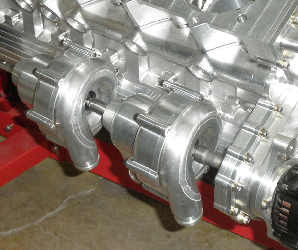
Figure 1: Tandem Coolant Pumps on Engine
Because of the counterclockwise crankshaft rotation and the accessory drive layout, I needed pumps that rotated counterclockwise.
Suitable coolant pumps proved to be unavailable, so I bought a high-performance pump from a leading supplier of high-efficiency coolant pumps, and had the volute and impeller laser scanned into a 3D CAD model, which I then mirror-imaged. I used that model to design a bespoke, high-performance pump with counterclockwise rotation which fits into my drive and performance envelope. Figure 2 shows the output characteristics of this pump design. At 6000 pump RPM, each pump can flow 100 gpm with a 35 psi rise, and 80 gpm with a 40 psi rise. The drive ratio (in the accessory case) has been set to optimise the anticipated flow rate and pressure rise requirements.
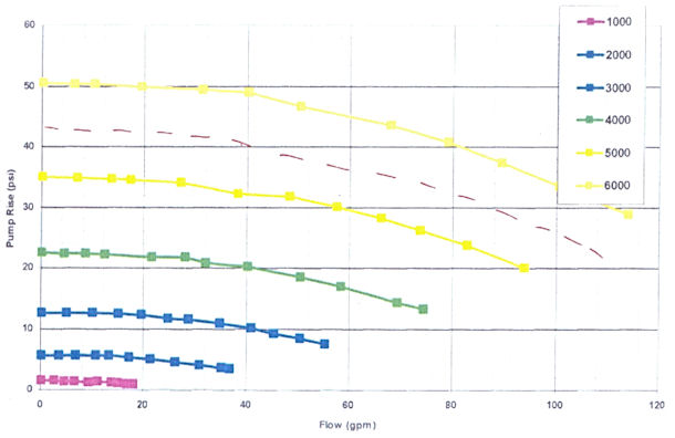
Figure 2: Coolant Pump Performance Curves - Flow vs. Pressure
The pump manufacturer made a couple of changes to my design in order to enhance manufacturability. The resulting parts, shown in Figure 3, are all CNC-machined from 6061-T6 billet. The seals and bearings are purchased parts.
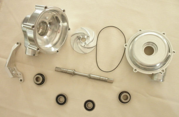
Figure 3: Coolant Pump Components
I decided to use two pumps in order to achieve the pressure rise needed to produce the required flow rate through the engine, check valves and thermostats, back to the heat exchangers (about 40 inches away, behind the cockpit), and then another 40-inch run forward, returning to the pump inlets.
There is a one-way check valve in the output path of each pump. Beyond the check valves, the flow from both pumps feeds into a junction box, which then feeds coolant into the center of each of the full length coolant galleries (shown in Part 2 and Part 8) on the outside of the block between cylinders 3 and 4.
With that check-valve-plus-junction-box system, a failure of one of the pumps will still allow the engine to be operated safely in order to get back to the ground.
In the block, coolant flows longitudinally in the center-feed coolant galleries. On the centerline of each cylinder, there is a coolant port perpendicular to the coolant gallery and also perpendicular to the cylinder axis. There is an orifice located in each of those ports. Each orifice is sized for its specific cylinder, regulating the coolant flow so as to maintain essentially equal coolant discharge temperatures in each cylinder’s coolant discharge chimney.
Coolant flows from the longitudinal galleries and circulates around the liners, then flows upward through evenly distributed passages around the top of the liners into circumferential channels at the top of each liner. From those channels, the coolant flows into the head through passages that are all on the exhaust (outer) side of the combustion chambers.
The cylinder head design is such that coolant completely surrounds both valve seats and the spark plug bore, and flows between the intake and exhaust ports where they blend into the combustion chamber roof. The monolithic core casting technology assures that all those channels and passages are correct and free from flash that might disrupt the flow.
In the cylinder head, there is a partial ‘ceiling’ across the top of the combustion chamber, parallel to the deck face and about 1/2 inch above the combustion chamber roof. It originates on the outer side of the head and extends inward toward the vee to about 1 inch inboard of the cylinder center axis. It is located close to the upper surface of the combustion chamber in order to maintain higher coolant velocities close to the hottest parts.
The ceiling directs incoming coolant across the combustion chamber surfaces and around both valve seats and the spark plug boss towards the vee of the engine. At the inboard end of the ceiling, the coolant reverses direction (away from the vee) and flows back towards the outer edge of the head, between the upper surface of the ceiling and the lower surface of the rocker box. There are no locations in the system that can trap any air, either when the system is initially filled or when entrained air evaporates out.
The exhaust ports are fully surrounded by coolant, whereas the exposure of the inlet ports to the coolant flow is limited to the area close to the combustion chamber and valve seats in order to minimize the transfer of coolant heat to the incoming charge.
Each cylinder has its own coolant exit passage (‘chimney’) at the outer edge of the head. Those passages flow upward into mating passages (one for each cylinder) in the billet aluminium rocker cover, exiting into a coolant gallery that runs horizontally the length of the rocker covers. The prototype rocker covers [Figure 4] have bosses in each chimney that accommodate pressure and temperature sensors to provide the data necessary to tune the coolant orifice sizes to optimise coolant flow for each cylinder.
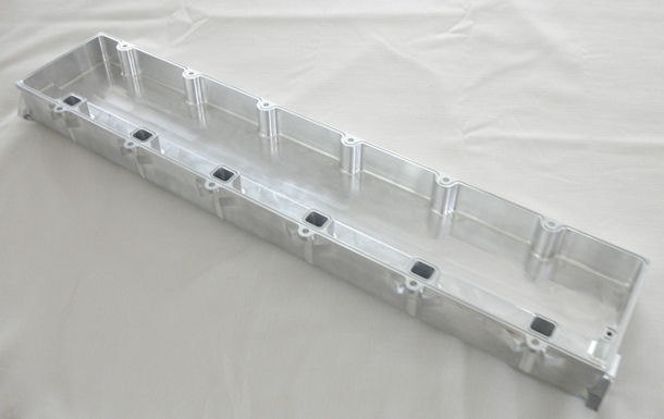
Figure 4: Billet Rocker Cover with Coolant Chimneys and Valvespring Oil Jets
The coolant from each rocker cover exite the longitudinal coolant gallery and converges in a thermostat housing that proportions the coolant flow to the main heat exchanger and to the coolant recirculation port as a function of the desired coolant temperature.
OIL AS A COOLANT
Discussion of the cooling system also requires addressing the engine heat carried off by the lubricating oil. Two major challenges in making a piston engine live for hundreds of hours at high power settings are the ability to extract heat from the pistons and rings, and from the valve springs.
For piston cooling, this engine uses a system of oil jets (mentioned in the Lubrication discussion), which spray multiple high-velocity jets of oil onto the underside of the pistons at the hottest portions of the crown.
The supercharged (1250 hp) version of the engine imposes a power load on the pistons of 8.06 hp/sq in of piston area. That is nearly identical to the load imposed by the pre-2015 unrestricted 890 hp Cup engines. I have seen versions of those engines that used as many as five oil jets per piston. I do not have that many in the V12, but the flow rate from the V12 jets is roughly equivalent to that provided by the Cup engines’ five jets. I am currently developing a new system to add one more jet per piston to the 1850 hp turbocharged race version.
Removing heat from the valvesprings is also critical. The springs operate at very high levels of cyclic stress, and generate a substantial amount of heat from the rapid cycling as a result of internal hysteresis. Further, they live in a hot environment, in contact with hot cylinder head surfaces on the bottom and with hotter valve stem components on the top.
To remove heat from those springs, each rocker cover has a full-length oil gallery, fed from the tertiary oil galleries in the block. Each gallery contains 12 cooling oil jets, each of which directly impinges onto one of the valve springs.
Oil is also the main cooling medium for the gearbox. A set of high-quality gears (AGMA-Grade 10) has been shown to consume about 1% of the transmitted power per mesh. Since this gearbox is a single-mesh, at 1850 engine hp we will need to remove about 20 hp (850 BTU/minute) from the gearbox.
The gears are cooled primarily by means of jets directed at the gears as they exit mesh. (Spraying oil onto gears as they enter mesh has been shown to generate measurable amounts of additional power loss.) Gearbox cooling is assisted by copious amounts of splash lubrication, supplied both by the directed jets and by the outflow from the gearbox plain bearings (covered in detail in the Gearbox section of this series).
Ambient air flowing over the gearbox housing can remove a significant amount of the gearbox heat, but the actual heat removal can vary dramatically as a function of ambient temperature, aircraft speed and the amount of ram air allowed into the engine compartment by the cowling. Therefore, the gearbox oil flow rate is sized for the worst-case heat rejection, which more than satisfies the lubrication requirements.
