Part 10: Supercharging and Turbocharging
Sizing and Selecting Compressors
NOTE: All our Products, Designs, and Services are SUSTAINABLE, ORGANIC, GLUTEN-FREE, CONTAIN NO GMO's, and will not upset anyone's precious FEELINGS or delicate SENSIBILITIES.
NOTE: EPI no longer has any involvement in this engine project. Project delays have occurred for a variety of reasons, resulting in conflict between EPI and the client. As a result, the Client-Contractor relationship has been severed by mutual agreement.
I am leaving these pages on the EPI website to describe the engine design details and technology for the general interest of our many readers.
Supercharger
Based on research of available products, I settled on Vortech superchargers because of the high-efficiency / high-flow compressors they offer. I designed the geared, torsionally isolated V12 supercharger drive to use a Vortech V30 drive gearbox, in which I have replaced the supplied bearings with high-speed, extreme precision bearings.
Before selecting a compressor, it is essential to know the flow and pressure requirements the compressor must satisfy.
The target net output power for the supercharged version of the engine was 1250 hp at 4800 RPM. In order to estimate the airflow required for 1250 hp, I used an Avgas fuel lower heating value of 19,000 BTU per pound of fuel burned. Since one hp is equivalent to 2545 BTU / hp / hour, then thermal efficiency equals (2545) ÷ (lower heating value x BSFC).
A BSFC value of 0.47 produces a thermal efficiency of 28.5%, which confirms the reasonableness of that BSFC estimate. Assuming a best-power air-fuel ratio of 12.6 and the 0.47 BSFC, it is straightforward to calculate the required mass airflow (79.9 lb/minute, or ppm) to produce the naturally aspirated (NA) power of 810 hp at 4800 RPM. That airflow number is confirmed by the simulation studies done during the initial design of the engine.
From that number, simple proportionality shows that 1250 hp would require 123.3 ppm.
However, that airflow is insufficient to produce the power necessary to run the supercharger and the various pumps and alternators attached to the engine, and still provide 1250 net hp.
The power consumed by the supercharger is a function of the airflow rate, the pressure rise and the compressor efficiency, as well as the losses produced by the power transmission system driving the compressor. Clearly then, determining the total hp the engine must produce to operate the compressor and accessories at a specified net power output is an iterative process, best done by a computer program.
I wrote a simple iterative program in which the user specifies the net power requirement, the fuel heat content and BSFC assumptions, inlet air conditions, estimated pressure drop across the intercooler and plumbing, and the compressor efficiency in the flow-and-pressure-ratio neighborhood of the requirements. The program calculates an initial guess at the compressor power requirement, then adds in the additional power required to drive the two alternators, the two coolant pumps at maximum flow, the engine oil pumps, the 1000 psi hydraulic pump for the aircraft landing gear, and the power consumed by the geartrain that drives the supercharger.
Airflow is only half of the picture. It requires a certain level of intake plenum pressure to force the required mass airflow through the engine. The program estimates that pressure by multiplying the 14.5 psia plenum pressure in the NA engine by the ratio of the total required power to the NA power.
The program iterates to find the actual airflow, then calculates the compressor power required as well as the actual pressure ratio required to deliver the required airflow through the intercooler to the intake plenum.
With those values and the known compressor RPM, one can locate the operating point in the compressor map, verify the efficiency and make the appropriate adjustments.
Using this calculation method, I determined that for a net output of 1250 hp, the required pressure ratio is beyond the range of the preferred compressor at the required airflow level. That caused me to lower the supercharged power output target to 1230 hp, which requires 138 ppm at a pressure ratio of 1.89, falling into the middle of the 80% island at the top pressure ratio line, and consuming just under 150 hp to drive the compressor.
I used that same method to estimate the power at lower RPM values, assuming roughly equivalent volumetric efficiency numbers and knowing the compressor operating point because of the fixed gear ratio. At 4000 RPM, the simulation shows 71 compressor hp, 114 ppm airflow at a pressure ratio of 1.58, for 1060 hp; and at 3600 RPM, 49 compressor hp, 103 ppm and a 1.44 pressure ratio for 970 net hp.
Plotting those points on the compressor map [Fig. 4] shows that the full-throttle operating line is nicely located in the high-efficiency central portion of the compressor’s range, roughly midway between the surge line and the choke line.
For operation at less than full throttle conditions, the ECU contains logic which operates a sonic nozzle system that bypasses a fixed amount of flow back to the inlet whenever the engine operating conditions (RPM and mass airflow) move close to the surge line.
The max pressure ratio this compressor produces is 1.89, right at the critical pressure ratio for air (ratio of specific heats = 1.4). The sonic nozzle therefore only chokes at maximum boost, and the amount of flow it bypasses at lower boost values varies with the boost level, which is effective for the intended purpose of establishing a margin away from the surge line.
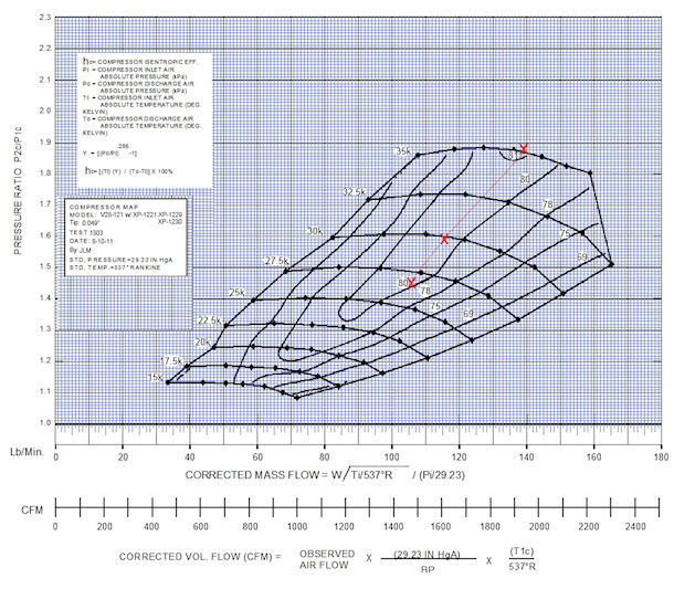
Figure 1: Vortech Compressor Map (Courtesy of Vortech Engineering)
It will be very interesting to see how close these estimates are to the actual results produced on the dyno.
Turbocharger
I initially selected a turbocharger based on the technology that was available when the engine design was completed several years back. That technology has advanced considerably since that time, so I am delaying final turbocharger selection until I am ready to begin testing that version of the engine.
However, for initial estimating purposes, using the same procedure as described above for the supercharger sizing, the estimated airflow requirement for 1800 HP is approximately 180 lbs/minute. I have not spotted a turbo that (a) can flow that much (b) at a pressure ratio in the neighborhood of 3.0 (c) at an adiabatic efficiency of 74% or better and (c) not be precipitously close to a rapidly downsloped choke line.
In view of that massflow requirement and of the currently available products, I am leaning strongly toward two of the Garrett GTX turbochargers. Using two of these smaller turbos greatly simplifies the red-hot-exhaust plumbing problems as well as the outflow and aftercooler plumbing issues.
There are two of initial interest, the maps of which are pictured below.
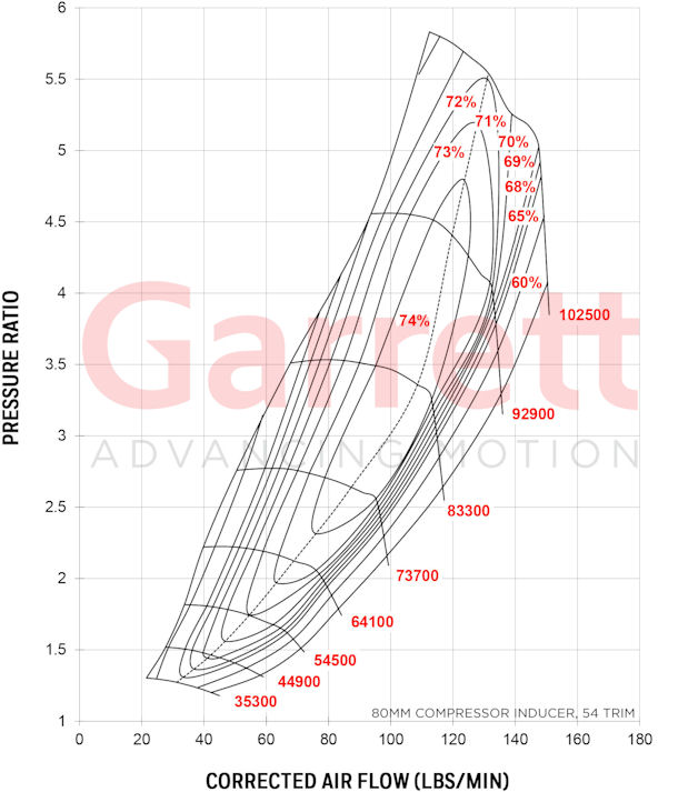
Figure 2:Garrett GTX-4709 Compressor Map
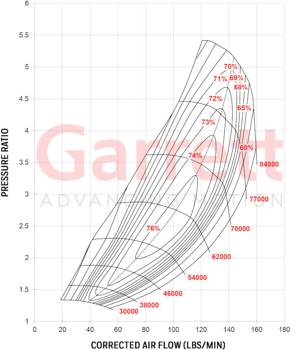
Figure 3: Garrett 5533 (85mm inducer) Vortech Compressor Map
The 4709 map gives me 90 lbm/minute at a pressure ratio of 3.0 right in the middle of the 74% island, but the choke line above that flowrate is very unforgiving. The 5533 / 85 also can flow about 90 lbm/minute at 74%, and the choke line is not quite as drastic.
When the time comes to select the turbos, there may well be additional improvements available.
