
- PSRU Design Methodology-
One Method (Not the ONLY Method !)
NOTE: All our Products, Designs, and Services are SUSTAINABLE, ORGANIC, GLUTEN-FREE, CONTAIN NO GMO's, and will not upset anyone's precious FEELINGS or delicate SENSIBILITIES
INTRODUCTION
This article is an effort to present the methodology that I use to design a propeller reduction gearbox. This methodology has produced several successful aircraft propeller reduction units, as well as non-propeller reduction gearboxes for helicopter, NASCAR, INDYCAR, industrial, and other applications. For non-propeller applications, the properties of the driven load are substituted for the propeller properties. The methodology remains the same.
I should point out at the outset that I am no longer in the manufacturing business. I sold the intellectual property for the Mark-15 gearbox several years ago, and I occasionally get inquiries about the purchase of other IP.
I make that statement to dispel any notion that this article is an effort to sell gearboxes.
DISCLAIMER
Clearly, the methodologies presented here ARE NOT THE ONLY WAY, but they are methods that I have found to work for me. I am providing this material for information-only, and not as a recommendation for any particular design, material, processing, configuration, or anything else.
The text, specifications, procedures, photographs, drawings, and any other artwork (hereinafter referred to as information) contained in this article is provided without any warranty as to its usability, performance, or suitability for any particular application.
Incorrect design, fabrication, processing, installation, and/or the use of aircraft and/or aircraft components are far beyond the control of the author and of EPI, Inc., and can result in injury or death.
Information presented in this article is based on the author’s real-world experience. The reader bears the sole responsibility for determining accuracy or suitability for use of this information.
The applicability of described procedures and / or configurations, both in software and hardware, and the qualifications of individual readers and users, are completely beyond the control of the author and EPI, Inc., and therefore the author and EPI, Inc. disclaim all liability, either expressed or implied, for use of the information in this article. All risk for the use of this information is assumed entirely and completely by the user.
In no event shall the author or EPI, Inc., be liable for any indirect, special, or consequential damages, including but not limited to personal injury, loss of property, or any other damages, arising from the use, incorrect use, or misuse of any information in this article or from any software described herein.
As you read through this article, you will realize that there is a considerable amount of actual engineering and analysis involved in the methodology described herein. You, as an experimental builder, can build and fly pretty-much anything that the Wishful Thinking School of Engineering can generate. However, that approach has proven to be unhealthful in far-too-many examples.
Beliefs and feelings don't alter facts.
It is also worth noting that having access to AND good skill with a competent 3D-CAD software package (with FEA) can be extremely helpful in this design process.
MAJOR SUBJECTS COVERED IN THIS ARTICLE
1. MASS MOMENT OF INERTIA
2. ENGINE EVALUATION
3. PROPELLER ANALYSIS
4. PROPELLER CONTROL
5. TORSIONAL EXCITATION PROBLEM
6. THE TV SOLUTION
7. INTRO TO GEARS
8. DYNAMIC GEAR TOOTH LOADING
9. GEAR FATIGUE
10. SPLINES
11. PLANETARY SYSTEMS
12. HY-VO SYSTEMS
13. BELT DRIVES
14. BEARINGS AND LUBRICATION
15. PROPSHAFTS
16. HOUSINGS
17. CONCLUSIONS
BACKGROUND
A propeller reduction gearbox is one of the MOST critical components in a geared Aero engine. The engineering literature is rich with information on the subject of propeller reduction gearboxes and problems therewith, especially those that are driven by a piston engine..
An American Gear Manufacturer’s Association (AGMA) publication summarizes the problem as follows:
“The gearbox is one component of a system comprised of a power source, a gearbox, driven equipment, and interconnecting shafts and couplings. The dynamic response of this system depends on the distribution of the masses, stiffnesses, and damping. In certain cases, a system may contain a torsional natural frequency close to an excitation frequency associated with an operating speed. Under these resonant conditions, the dynamic gear tooth loads may be very high, and operation near a system resonance is to be avoided.”
In Volume 2 of his renowned reference work The Internal Combustion Engine in Theory and Practice (Library Reference 5 : 3 : 280) , C. F. Taylor says this about propeller gearboxes:
“Particularly complex is a vibration system consisting of a piston engine with an air propeller mounted on its output shaft, since the propeller blades usually have important modes of vibration which tie in with crankshaft torsional vibration.”
Clearly, a propeller gearbox cannot be treated as an isolated entity. It is a critical component in a vibration-rich system that has two major sources of excitation (the engine and the propeller) and at least two natural frequencies, in addition to the internal natural frequencies of the engine crankshaft system and elements of the propeller itself. Any change to any part of the system can significantly alter the vibratory loadings imposed on the other parts of the system.
However, in addition to the vibration issues, there are other design considerations that must also be taken into account to ensure a sound design.
MASS MOMENT OF INERTIA
Mass Moment of Inertia (MMOI) is an important design concept, and it is referenced throughout this analysis. If you are unfamiliar with the concept, it is well-presented IN THIS PAPER, as well as in numerous physics and machine design textbooks. Section 7.4.2 of that linked article presents a table showing the equations for the MMOI of common geometric shapes. So in the absence of a 3D-CAD package, a rotating system can be divided up into adjacent common sections, and the MMOI for each section calculated and summed.
The MMOI of components can also be measured. One effective method, known as the "tri-filar" (three strings) pendulum method, is discussed in detail HERE.
Regarding MMOI units mentioned in the flywheel discussion below, my 3D-CAD package (SolidWorks) produces MMOI in the units pounds-inch². The units that work with my calculations are inch-pound-second². Without getting into a discussion of pounds-mass vs. pounds-force, the conversion is as follows:
386.088 pounds-inch² ÷ ( 32.174 x 12 ) = 1.000 inch-pound-second²
where 32.174 is the standard acceleration of gravity, in ft/sec², 12 is the number of inches in one foot, and those two numbers in the divisor can be combined into 386.088 - - - ( 32.174 x 12).
ENGINE EVALUATION
As a first step, the selected engine should be characterized. If you are building a custom engine, then dyno-testing for torque and power curves, as well as for fundamental reliability evaluations, should be considered mandatory.
And if you are building your own engine, be careful to select a cam, intake runner lengths, and exhaust runner lengths that will locate the torque peak near the projected cruise engine rpm. Avoid "low rpm torque" cams. You want a torque curve that is fairly flat from cruise to max power. It doesn't matter if the torque curve drops sharply after peak power.
For the various incarnations of GM Crate Engine V8's (LS, SBC, BBC) often considered, GM publishes power / torque curves for most of them. Probably other manufacturers do that too - I don't know.
If you have an engine simulation software package, you MIGHT be able to get reasonable power and torque curves. That depends on a variety of factors, including:
- how good is your sim package (there are several out there; some are hopelessly optimistic), and
- how accurately you can parameterize your particular engine, including:
- tables of cam lobe lift every degree,
- tables of port flow every 0.050 of lift,
- intake and exhaust system characteristics - flow numbers, runner lengths and diameters, collector characteristics,
- valve spring rates and weights,
- valve sizes and weights,
- accurate rocker geometry (if applicable),
- weights of pistons, pins, rings, big-end and small ends of the conrods,
- bore, stroke, static compression ratio,
- etc. etc.
Based on your engine output curves, and on known (or hoped-for) reliability data for the selected engine, the maximum and cruise engine RPM values should be determined, based on:
- keeping the MAXIMUM mean piston speed below 3000 feet per minute, (and preferably below a maximum of around 2800 feet per /minute), and
- selecting an operating range in the torque curve that, if the torque curve is quite flat around the peak, the max and cruise numbers should straddle the peak, or be biased one way or the other, as YOU prefer.
Depending on the shape of the torque curve, another option would be to put the cruise RPM at or near the peak torque.
NOTE that those statements are made with reference to large displacement engines operating at moderate RPM levels (below approximately 5500). Smaller engines operating at higher speeds MIGHT be optimized differently. Examination of the specific power and torque curves will provide the answers.
In order to do a good torsional analysis, the Effective Mass Moment of Inertia (EMMOI) of the selected engine at the output end of the crankshaft must be determined (along with other parameters described later in this article).
That EMMOI value is a composite of calculations (or measurements) of the engine components, including (a) the effect of the rotating / reciprocating assembly, (b) engine-driven accessories, and (c) the flywheel system.
The engine EMMOI can be accurately estimated from calculations that take into account the number of cylinders, the engine stroke, the masses of the rotating and reciprocating components (bobweight), and the MMOI of the various engine-driven accessories (crankshaft vibration absorber, alternator, coolant pump, etc.), and of course, the flywheel system.
The MMOI's of the crankshaft, bobweights, and driven accessories transfer to the output end of the crankshaft by about 2/3 of their actual value.
This estimation method has shown remarkable accuracy when compared to known engine values.
A large engine EMMOI is a major contributor to an effective torsional isolation system. The primary influence on that value is the flywheel design. The flywheel system does not need to be heavy, it simply needs to have a large MMOI.
One method to achieve that goal is shown in Figures 1 & 2.
It consists of:
- a round flywheel plate made from a high-strength aluminum alloy,
- an inertia ring, made from a high-strength steel alloy, that is attached to the outer portion of the round plate,
- the appropriate starter ring gear, shrunken AND Loctited onto an appropriately-sized diameter on the inertia ring (the journal diameter for a 14 inch, 168-tooth ring gear is about 0.015 larger than the ID of the gear), and
- a splined drive hub, also from a high-strength and appropriately-heat-treated steel, that clamps the flywheel plate to the output end of the crankshaft, and drives the gearbox input shafting.
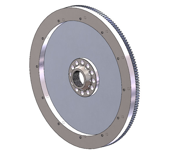
Figure 1 - High MMOI Flywheel
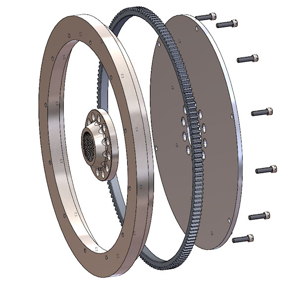
Figure 2 - Exploded View of High MMOI Flywheel
The properties of the resultant flywheel system are available in your 3D-CAD design, or, in the alternative, can be easily calculated using the analysis methods presented in most basic physics texts (for example Library Reference 1 : 10 : 163-166).
NOTE that when designing the inertia ring, to achieve the maximum available MMOI in the available space, the OD should be as large as you can fit into the envelope; the ID should be as close to the OD as is practical (typically a 2-inch difference can work) and the axial width should be as large as practical, given the tradeoff between weight and required MMOI.
The flywheel system shown in Figures 1 & 2 has a MMOI of 638.1 pounds-inch² (1.653 inch-pound-second²) yet weighs only 17 pounds.
Sometimes it is not appropriate to design an aluminum-plate-with-inertia ring as described above. A good example of such a situation is the VW Type 1 engine, in which the flywheel (a) is attached to the crankshaft by a huge gland-nut, (b) is anti-rotated by 8 stout dowel pins, (c) contains an integral starter ring-gear, (d) has a boss that centers the flywheel on the output diameter of the crankshaft, the OD of which also serves as the surface upon which the rear main crankshaft seal operates.
An OEM example of that flywheel is shown in Figure 3.
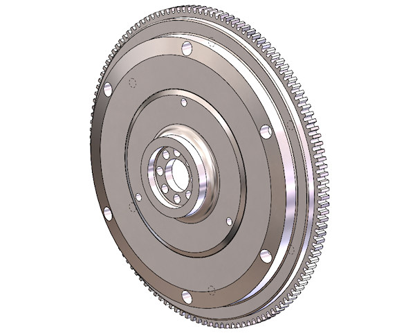
Figure 3 - OEM VW 8-Dowel Steel Flywheel
In this sort of an application, it could be possible to machine an inertia ring and shrink-fit it or bolt it to the OEM flywheel to increase the MMOI.
That is how I modified an OEM flywheel for a VW project that I did. I drilled lightening holes in the inner-radius portion of the flywheel, machined off a bit off the thickness, and then machined a custom intertia ring (the blue component) and shrunk & Loctited it onto the modified flywheel. That modified version is shown below in Figure 4.
The OEM flywheel (Figure 3) weighed 14.02 pounds and had an MMOI of 224.8 pounds-inches². The modified version (Figure 4) weighed only 16.25 pounds but had an MMOI of 294.9 pounds-inches². That represents a MMOI increase of 31% for only a 16% weight increase. For this application, it was necessary to modify an existing steel flywheel in order to retain the unique flywheel-to-crankshaft attachment method and starter gear location.
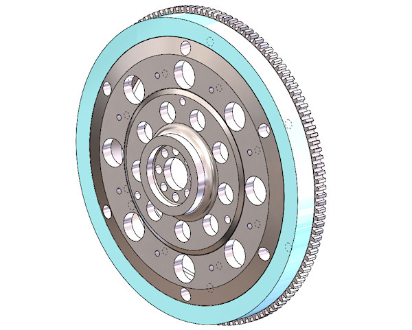
Figure 4 - High-MMOI VW 8-Dowel Steel Flywheel
The shrink-fit procedure I used for that inertia ring were:
- machine the inertia ring 10 thousandths (0.010) less than the OD of the flywheel journal diameter,
- heat the ring in an OVEN (NOT wih a torch) to about 275°F (do not exceed 300 °F, especially with shrinking a separate ring gear onto a journal, such as shown in Figures 1 & 2 above),
- let the heated part soak in the 275°F oven for an hour to be sure it has reached equilibrium,
- clean the OD of the journal with acetone,
- apply a THIN coating of red Loctite (262, 271, or equivalent) to the OD onto which the inertia ring (or ring gear) will go,
- when the ring has stabilized at the target temperature (determined with a $15 infra-red temperature gun) you can grab it with two sets of pliers and drop it onto the OD where it is destined.
- the ring SHOULD drop right onto the journal, and seat squarely against the shoulder.
Here is another very clever way that a friend increased the MMOI of an existing low-MMOI (aluminum disc) flywheel for his substantially-modified / improved Turbocharged Subaru EJ-22T (2.2 liter) closed-deck boxer engine that produces about 185 lb-ft of torque at SL / STD takeoff setting. That engine has, as OEM parts, a forged crank, forged conrods, piston oil squirters, and a higher-capacity oil pump.
In this flywheel mod, each cylindrical steel weight fits into a carefully-machined 0.100 deep recess in the flywheel disc in order to assure that the attaching bolts are not loaded in shear.
He flew with the lightweight-version of the flywheel for some time, and experienced noticeable powerplant vibrations. After the mod, reported that the vibrations from the powerplant diminished remarkably.
BUT AGAIN, do not be misled by the MISTAKEN BELIEF THAT "IF YOU CAN'T FEEL VIBRATIONS, THEN THERE MUST NOT BE ANY". Destructive torsional excitations mostly occur in frequency ranges beyond human sensory bandwidth.
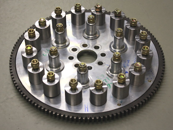
Figure 5 - High-MMOI Flywheel Method - Courtesy of Ross Farnham, SDS EFI Systems
PROPELLER ANALYSIS
The next major system component to be considered is the propeller. Presumably the gearbox designer will have selected a propeller candidate for the target aircraft. ALSO, the designer should have a reasonable estimation of the maximum and cruise true airspeeds that the target aircraft can be expected to achieve.
THIS ARTICLE presents a thorough discussion of propeller performance parameters and selection criteria, and is briefly outlined below.
In order to arrive at an optimal reduction ratio, it is necessary to determine the RPM range of optimal propeller performance (efficiency) in your application.
That study is done by using the propeller performance map (from your prop manufacturer) for the specific propeller you have selected.
A performance map is typically a two-dimensional table of propeller efficiency values, with POWER LOADING as the X axis and ADVANCE RATIO as the Y axis. Using the performance map, you can determine the propeller efficiency at any power input level and any aircraft velocity.
The easiest way to do this study is to transcribe the propeller efficiency values and X-Y axis parameters from the manufacturer's map into a two-dimensional table in Excel, then, write the following two equations in the spreadsheet.
POWER LOADING (Cp) = ( HP * 550 ) ÷ (AD * N^3 * D^5)
ADVANCE RATIO (J)= TAS ÷ (N * D)
The five variables in those two equations are:
- TAS (Aircraft True Airspeed in ft/sec),
- N (Propeller Speed in Rev-per Second, which is RPM ÷ 60),
- HP (Power applied to the propeller - engine HP will do),
- D (Propeller diameter in feet),
- AD (air density in slugs-per-cubic-foot - sea level std = 0.002376).
Input YOUR values of those five parameters into the two equations, and use the resulting Cp and J values to interpolate the efficiency table for the value at those conditions. Doing those calculations for a number of different (anticipated) aircraft flight conditions will provide a range of optimal propeller RPM values.
Once the intended propeller has been evaluated as described here, the MMOI of that propeller must be obtained.
IF, FOR WHATEVER REASON,
you decide against using a performance map to evaluate YOUR PROPELLER for YOUR AIRCRAFT, then, at least do the following calculations for propeller tip speed in order to approximate the suitability of your chosen propeller.
There is a comprehensive discussion of propeller tip speed HERE, but in summary, tip speed is a helical velocity (ft / sec) which is the vector-sum of:
- propeller rotational speed in feet-per-second is (Vr = prop RPM * diameter {ft} ÷ 19.1) , (where 19.1 is 60 ÷ pi ), and
- aircraft forward speed in feet-per-second is (Va = KTAS * 1.688).
Therefore, tip speed (Vt) is - - - Vt = SQRT ( Vr² + Va²).
The "limiting" nature of tip speed is that after tip speed exceeds (typically) Mach 0.84 to 0.88, the efficiency of the propeller at converting power to thrust drops dramatically.
Mach-1 is the local speed of sound, and is strictly a function of absolute temperature, calculated as:
M1 = 49.02 * SQRT(460 + OAT{°F}).
Therefore, tip mach = Vt ÷ M1.
Your objective would be to determine the maximum RPM that the candidate propeller can use at the maximum true airspeed and minimum air temperatures the target aircraft is expected to attain, in order to keep the tip speed below approximately 0.84 to 0.88 Mach.
A simple Excel program can do that easily, especially if you include a table of standard atmospheric temperature vs. altitude, and interpolate that to get standard OAT at altitudes, then subtract an estimated amount for cold days at the selected altitude.
Having determined that the diameter of your selected prop is appropriate for your target aircraft, and having determined the maximum reasonable propeller RPM, you also need (as noted above) to get the propeller MMOI from the manufacturer.
If your propeller manufacturer DOES NOT HAVE a PERFORMANCE MAP or an MMOI VALUE for your selected propeller, perhaps you should consider a different manufacturer.
PROPELLER CONTROL
The typical single-acting hydraulic propeller governor contains a flyweight-based speed sensor and resisting spring ("speeder spring") that moves a hydraulic valve that meters pressure to the propeller hub. The governor also contains a boost pump that increases the supply of engine oil pressure (typically approximately 40 to 80 psi) to about 250-300 psi for operating the propeller pitch control piston.
The hydraulic prop governor described above can apply a substantial torque load to the governor drive system.
In my typical governor drive system, the governor drive gear attaches to the back of the output shaft, and the driven gear and governor drive shaft are at a right angle to the propeller shaft. I have designed several different sets of crossed helical gears, in a material proven to have a long life in that application, to provide the nearly-optimal max governor RPM of 2700, regardless of the gearbox reduction ratio.
My gearboxes for controllable propellers use the standard AND-20010 propeller governor interface, with a torsionally-isolated crossed-helical gear drive and fully internalized hydraulic plumbing. NOTE: There are special considerations that are essential for a crossed-helical gearset to survive. Those constraints are discussed in the GEARS section below.
FWIW, in one of my earlier designs, I built a toothbelt-driven prop governor drive that mounted to the front of the engine and was driven by a sprocket attached to the front of the coolant pump. That, of course, required additional housings, bracketry, and (messy, failure-prone) external plumbing.
GEARBOX PRELIMINARIES
Now, having determined the optimal engine RPM band from your engine performance curves and the optimal prop RPM for your anticipated cruise and max speeds, you are ready to select the appropriate gear reduction ratio for your system.
Reduction Ratio = max engine RPM / max propeller RPM.
Having determined the desired reduction ratio, an appropriate reduction system (Gears, HyVo, Belts, Magnetism, whatever) must be designed, taking into account the vertical offset distance desired between the crankshaft centerline and the propshaft, as well as the desired direction of rotation of the propeller (same diection as the crankshaft, or opposite, discussed HERE).
Having done a preliminary design of the reduction system, the MMOI of the components (drive gear, idler if used, output gear, pulleys, sprockets, etc) can be determined.
Next, a preliminary design of the propshaft should be done. From that, the MMOI and torsional rate of the propshaft, from the prop flange to the gear-mounting flange or spline can be calculated.
With these basic, preliminary values in hand, the solution of the torsional problems can begin.
THE TORSIONAL EXCITATION PROBLEM
The instantaneous torsional signature of a spark-ignited piston engine is not a smooth constant-torque line, but rather a waveform that contains significant peaks and valleys that extend above and below the mean (measured) engine output torque.
(NOTE: Ccompression-ignition engines and rotary ("Wankel") type engines present a much more difficult problem because of their huge rate-of-change in combustion pressure compared to that of a spark-ignition, piston engine.)
Figure 6 shows the signature of an even-fire 8-cylinder engine. The amplitudes of the evenly spaced fourth-order torque pulses (four firing events per revolution) are roughly ±90% above and below mean torque, but do not go negative. Engines with fewer cylinders, and with uneven firing orders can go well into negative territiry .
Figure 6: Torsional Signature of Even-Fire 8-Cylinder Engine
Even-fire engine configurations having fewer than 8 cylinders produce lower excitation orders and higher amplitudes, some of which cross below zero torque (torque reversal). The lower orders are more difficult to attenuate.
Worse yet, odd-fire engines produce combinations of higher and lower orders that are even more difficult to deal with.
Examples of some common engine torsional signatures and explanations of their configurations are discussed in detail HERE.
From Figure 6, it is easy to see how the components driven directly by a piston engine would be subjected to torque pulses that can be a significant multiple (+/-) of the mean engine torque. That pulsing subjects them and their driven mechanisms to additional cyclic fatigue loading imposed by the varying torque.
It is important to isolate the gears and propeller from the torsional pulsing of the engine, for several reasons.
FIRST, gear teeth (and chain links) experience a significant fatigue-loading profile when driven by a motor having a constant torque output (electric, turbine, etc.). Gear teeth that are transmitting a pulsing torque curve are exposed not only to the zero-to-peak-to-zero fatigue cycling that would occur if the torque was a constant value, but also to the added rising and falling component of the waveform as it cycles above and below mean torque, and thus to the additional gear tooth contact and bending loads.
SECOND, if the engine excitation is anywhere near a system resonant frequency, the load pulses that are applied to the gears will be multiplied, sometimes by as much as a factor of 10.
THIRD, if the torsional excitation is anywhere close to a resonant frequency of one of the driven components (the connection between the engine and gearbox, the gearbox components, the propeller blades), destructive vibrations of those components can be triggered.
As an example, visualize what happens to a propeller blade that is subjected to a pulsing drive torque. During the positive portion of a torque pulse, the blade will deflect in the plane of rotation so as to fall behind its theoretical position, acting as a spring and storing energy. Then during the negative portion of the torque pulse, the blade will rebound, releasing that stored energy, and deflect forward of its theoretical position, storing a new glob of energy. That cycle continues.
If the excitation frequency is close to the natural frequency of the blade, the excitation continues to add energy to the vibrating system, causing the ampllitude of deflection (and thus the bending stress level) to continue to increase.
If the duration of that exposure to resonant excitation is significant, one of the blades will fail in fatigue (probably at the root, but failures have also occurred at various locations along the blade) and depart the aircraft.
The resulting out-of-balance will be of such a huge magnitude that it will very likely tear the entire engine off the airframe and likely ruin the remainder of the pilot’s day.

Figure 7: Result of a Propeller Blade Fracture
THE NEED FOR ISOLATION
Isolation from the pulsing drive torque can be accomplished in different ways. Certain compression-ignition engines use a spring-mass system incorporated into the flywheel, that is tuned to the excitation frequency of major concern (the ‘dual mass flywheel’). It operates on the same principle as the common vibration absorber found on the nose of most crankshafts (not "damper" except in the case of the FluiDampr™). The problem with that approach is that it is only effective at the tuned frequency (and its harmonic multiples).
I think a better approach is to use an engine-to-gearbox coupling that exploits the property of transmissibility, discussed in detail HERE and HERE, and removes most of the excitation across a wide frequency band.
Summarizing, transmissibility is the ratio of the vibratory force applied to the input of a system to the vibratory force produced at the output of the system (FORCE RATIO). My systems provide an engine-to-gearbox coupling that has very low transmissibility throughout the entire high-power portion of the operating range. That reduces the engine torque pulses to very low amplitudes at all frequencies of interest, and those frequencies are, by design, far away from system resonant frequencies.
In order to better understand this principle, Figure 8 shows a plot of transmissibility as a function of frequency ratio (r, the ratio of the excitation frequency to the resonant frequency) at different damping ratios (β, the ratio of the existing damping to the critical damping for that system).
Figure 8: Plot of Transmissibility vs Frequency Ratio for Various Damping Ratios
Figure 8 illustrates three important concepts.
- - FIRST, in a driven system with zero damping that is operating at the resonant frequency, the transmissibility (FORCE RATIO) goes to infinity. If you add a substantial amount of damping to the system, nevertheless, at frequencies near resonance the transmissibility is always greater than one, which means that the pulsating input forces are being amplified, sometimes by a very large amount. (In practical systems, the transmissibility rarely goes to infinity because nearly all the components possess some amount of internal damping.)
- - SECOND, at a frequency ratio above 1.414 (‘crossover’), the force ratio drops below 1.0, and at a frequency ratio above 3.3 with zero damping, the transmissibility drops below 0.10 (10%). Therefore the amplitude of the vibratory forces transmitted to the gearbox is attenuated to below 10% of the engine excitation amplitude, and that fraction can approach 1% at higher frequency ratios.
- - THIRD, it is clear that damping needs to be minimized in order to achieve the very low transmissibility values that reduce engine excitation to a mere ripple.
The principles outlined here show that by moving the crossover point to as low a frequency ratio as practical, and by minimizing the damping in the system, the transmissibility at high frequency ratios can become very low (less than 0.05) and the driven load becomes isolated from the vibration induced by the engine.
HOWEVER, despite the fact that a low transmissibiility system reduces the pulse-loading on the gearbox components, and on the propeller, nevertheless, there is STILL PULSING being applied, and that pulsing can still act as a vibratory excitation to the propeller blades if the pulsing frequency is close to a blade resonant frequency.
THAT is why it is important to do an instrumented vibration survey on the whole system, across its entire range of operation. Think about that - - changing the propeller on a stable system to another propeller with different vibration properties can change that system into a very UNSTABLE one.
Note that "DAMPING" is a crutch that is effective at reducing driven vibrations IF one must operate below crossover. However, above crossover, the low transmissibility cannot be achieved if there is any significant damping in the system.
NOTE: the term ‘DAMPING’ is frequently misused. The property of “damping” enables a system to dissipate energy, usually by conversion of kinetic (motion) energy into heat energy, explained in detail HERE.
The misnamed automotive device known in parts of the world as a shock absorber is a common example of a damper, and is known as a "damper" in the UK and elsewhere.
For anyone interested, the following is the equation for transmissibility, using the parameters "frequency ratio" and "damping ratio". Frequency ratio (r) is the ratio of the frequency of interest divided by the system resonant frequency. Damping ratio is the ratio of the amount of damping in the system divided by the critical damping value for the system under consideration. More detailed presentations on these quantities can be found in several textbooks on vibration, including Mechanical Vibrations by Den Hartog, and Mechanical Vibrations by Tse, Morse, and Hinkle (which can be downloaded for free in PDF format).
Transmissibility = Sqrt(1+(2*ß*r)²)/Sqrt((1-r²)²+(2*ß*r)²)
Clearly, to solve that equation, you must have first determined the resonant frequency of the system you are analyzing. That subject is covered in detail below.
TORSIONAL ISOLATION RESULTS
Figure 17 shows a plot of the transmissibility of my V12 engine in race configuration, using the most-likely propeller, and assuming a damping ratio of 0.15. Note that above 1950 ERPM, the transmissibility is below 0.10, and above 4900 ERPM it falls to less than 0.03.
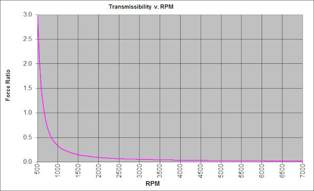
Figure 17: Transmissibility for the V12 Powerplant in Race Configuration
THE SOLUTION
The final dynamic analysis of this system is determined from a set of parameters that define the characteristics of a SPECIFIC SYSTEM.
For an engine-gearbox-propeller system, the analysis parameters are:
- The Effective Engine MMOI (J), including the engine rotating and reciprocating masses, the total flywheel MMOI, and the (reduced) effective MMOI of accessories driven by the free end of the crankshaft (in-lb-sec²);
- The effective MMOI of the driving gear, idler gear (if any), and any rotating shafts and bearing components;
- The Effective MMOI of the propshaft, output gear, and any rotating bearing components;
- The Effective Propeller MMOI (in-lb-sec²), typically obtained from the propeller manufacturer;
- The Effective Torsional Rate of the gearbox input system (between the end of the crankshaft and the driving gear, including spring elements, elastomer elements, and torsion shaft elements (lb-ft-per-degree);
- The Effective Torsional Rate of the propshaft between the output gear attach mechanism and the propeller attach flange ( lb-ft/°);
- The gearbox reduction ratio;
- The excitation order to be investigated.
The engine-gearbox-propeller system can be simplified into a three-degrees-of-freedom system [Figure 9] consisting of three equivalent "flywheels" and two shafts.
The "Equivalent Engine" flywheel has the Effective Mass Moment of Inertia (EMMOI) of the complete engine at the flywheel end of the crankshaft, including anything attached to the "free" end of the crankshaft (explained above).
The "Equivalent Gearbox" flywheel has the composite EMMOI of the gearbox (input shafts and gear, idler gear).
The "Equivalent Propeller" flywheel has the EMMOI of the driven load (propeller, output gear, output shaft) mathematically transferred to the engine axis by the square of the inverse gear ratio.
For example. a gearbox with 21 driving teeth and 58 output teeth has an inverse ratio 21 ÷ 58 = 0.362 (which is 1 ÷ the "commonly-stated" ratio 2.76, or the "inverse" of the common ratio). So if the propeller MMOI is 38.4 in-lb-sec², then the value referred back to the engine axis is 38.4 * 0.362 *0 .362, or 5.03 in-lb-sec².
That demonstrates the strong effect that the gearbox reduction ratio has on the solution because the actual masses and rates of the driven components (propeller, shafts and gears) are reduced by the square of the inverse reduction ratio.
The first shaft (small diameter in the picture) has the net torsional rate of the connection between the engine and gearbox. The second shaft has the net torsional rate of the connection between the output gear and the propeller system multiplied by the square of the inverse gear ratio (as defined in the previous paragraph).
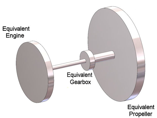
Figure 9: Equivalent Vibrating System
The mathematical solution for the resonant frequencies is fairly straightforward using the using the Holzer method, and can be implemented in a straightforware Excel spreadsheet.
The resultant transmissibility values enable an iterative design process in which I adjust the component properties (MMOI's and torsional rates) so as to achieve the design target frequencies and stress levels, then try to design components that actually have those properties.
In practical terms, the goal is to move the first mode resonant frequency to below the engine excitation frequency at engine idle, and move the second mode to at least twice the excitation frequency at maximum propeller RPM.
Achieving the desired first and second mode resonant frequencies is achieved by tailoring engine EMMOI and the torsional rates of the input and output shafts.
(NOTE: It would be ideal to move the second mode to below engine idle as well, but the resulting physical properties of the gearbox elements would be entirely unsuitable to support propeller thrust, driving torque and gyroscopic moment loads.)
The need for a high MMOI flywheel system has been covered above. The other major component of the isolation solution is achieving a low torsional rate between the engine and the drive gear in the gearbox.
I have been able to achieve the required strength and torsional rate in the engine-to-gearbox connection by the use of shafting made from an extreme-strength alloy (300-M-VAR, aka AMS-6419), using a known, precise heat treatment process, drawn from ASM Handbooks, Volumes 1 and 4, and reproduced HERE, to achieve a tensile strength of 290 ksi, a yield strength close to 240 ksi, and fracture toughness that substantially exceeds that of steels used for oil-well drilling bits.
That metallurgy provides extreme torsional strength while enabling suitably low torsional rates needed for vibration isolation. I limit the working torsional stress level in these 300-M shafts to 55 ksi.
The input shaft system I use consists of two hollow co-axial shafts, in series, inside the drive gear. Using that approach, I have been able to achieve torsional rates as low as 35 lb-ft per degree at reasonable stress levels for the application-specific applied torque. An example of those three components is shown in Figures 10 and 11 below.
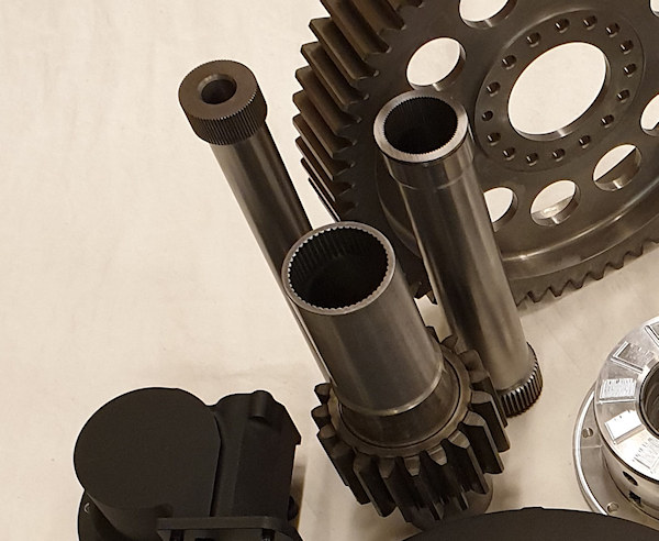
Figure 10: Co-Axial Input Shaft System
Here is a cross-sectional view of one set of those input components.
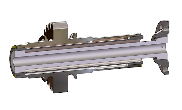
Figure 11: Co-Axial Input Shaft System Cross-Section View
The torsional rate of a shaft is determined by the fourth power of the OD and ID of the cross section { the polar moment of inertia = pi ÷ 32 * (OD^4 - ID^4) }, and is linearly proportional to the length of the torsional section. That should explain the need for co-axial shafts to obtain the needed rate.
The equivalent rate (Ke) of springs ( K1, K2, K3,.....) in series (such as two coaxial input shafts) is:
Ke = 1 / ((1/K1) + (1/K2) + (1/K3) + ....)
In the design of those co-ax shafts, it is extremely important that the critical speed of each is well above (1.5 X or more) the maximum engine RPM that will be used.
Critical speed is the RPM at which the natural-but-miniscule deflection of the shaft that occurs because of its own weight and stiffness generates enough out-of-balance due to centrifugal force, that the shaft becomes unstable and vibrates, often destructively. The inner shaft of the co-ax set is more likely to have that problem because of the much smaller polar moment of inertia of the cross-section. A detailed treatment of shaft critical speed can be found in Machinery's Handbook (Library Reference 2 : 22 : 198-199)
Another method I have used to achieve the required low-torsional rate between the engine and gearbox is to combine an appropriate clutch-disc spring center in series with a low torsional rate shaft. That solution can be used IF a clutch center can be found that:
- has the required torsional rate,
- has sufficient deflection range that the springs WILL NOT COMPRESS TO SOLID HEIGHT until well past the maximum anticipated peak applied torque, and
- has a sufficiently robust internal spline that can accommodate a mating external spline that can carry the maximum applied torque at an appropriate stress level (discussed in the section on SPLINES below).
The first two requirements { (a) and (b) } can be measured with a fairly simple fixture and a calibrated torque wrench.
The third requirement will require some calculations ( explained below under SPLINES).
The spring center and the connecting shaft are a pair of springs in series, and their torsional rates combine to provide a much lower torsional rate (as described above).
An example of such a solution is shown below (Figure 12), using an off-the-shelf clutch disc with the linings and rivets removed, bolted to the clutch face of the modified VW flywheel described above (Figures 3 and 4).
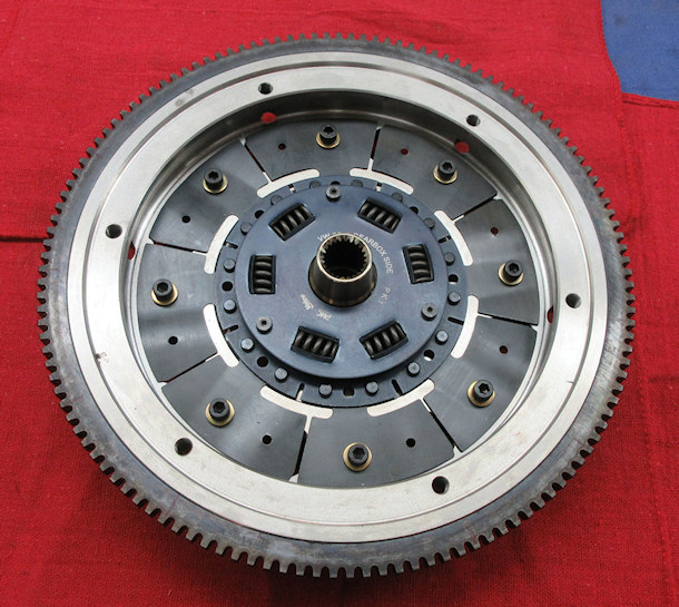
Figure 12: EPI Modified 8-Dowel Flywheel with Spring Drive
It was recently pointed out ot me that the operation of this spring-center clutch disc is unclear to some readers. That is a real puzzler, but in order to alleviate that "unclarity", the following picture (Figure 13) shows an exploded view of the above-described modified clutch disc.
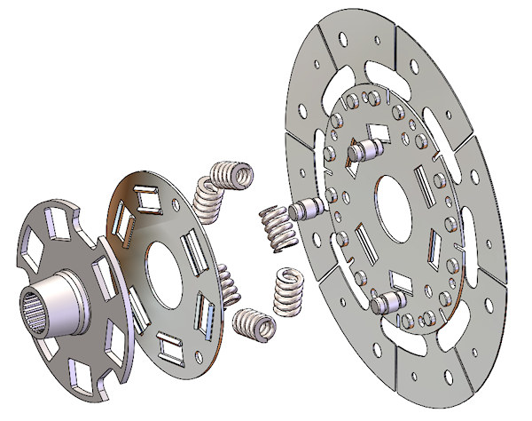
Figure 13: Exploded View of Spring Drive
This concept is hardly a new one. One example is the magnificent Pratt & Whitney R-2800 radial, designed in the late 1930's, which used a similar concept with the spring-center cushion in the supercharger drive, which had to transmit prodigious amounts of power to the supercharger, but at the same time had to absorb the torsional excitation from the engine. Because of the internal friction in that device, there was most certainly some amount of true damping that it provided as well.
The following picture (copied with great respect from Graham White's superb book "R-2800 - Pratt & Whitney's Dependable Masterpiece" ) shows the details of that drive.

Figure 14: P&W R-2800 SUpercharger Drive Cushion
Another device I have used occasionally to provide the necessary torsional connection between engine and gearbox is the Giubo ("JEE-OOO-BO", not "GWEE-BO") coupling. This method is very useful when the gearbox is mounted a distance from the engine, and hence needs to be connected by a driveshaft. These couplings are used as a combined U-joint-and-torsional cushion on various European sedans (and others, I would imagine). A picture of this sort of coupling is below.
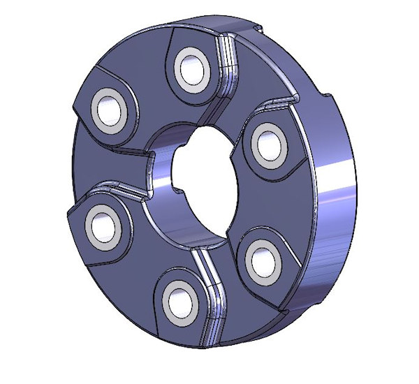
Figure 15: SGF-GAB-87-1-0391-020 Flexible Coupling
The manufacturer of the joints I have used in the past is a German firm, SGF. I have a table of technical specifications for more than 75 of the joints they produce, including working torque, failure torque, torsional rate, MMOI, maximum speed, and physical dimensions. I have studied these products with the goal of replacing the expensive co-ax shaft solution with a much less complex and far less expensive solution using ONE of these joints. The problem I encountered was not finding a single joint that has the necessary combination of (a) the required torsional rate, and (b) the required working torque. However, that solution work well with a driveshaft application in which there is a joint at each end, and the two torsional rates combine as described above.
GEARS
Gearbox purveyors often advertise the horsepower that their unit is claimed to handle. However, that is basically uninformed marketing hype. The power which is transmitted through a gearbox is only of interest for determining heat rejection (cooling) requirements, and is essentially meaningless in terms of the loads applied to the internal components.
There is a quick course in gear terminology and design HERE.
When selecting a gearset to achieve a particular ratio, it is important that the driven gear tooth count never be an even multiple of the driving gear tooth count, in order to implement the "travelling tooth" principle. That produces a gearset in which each tooth on the driving gear contacts a different tooth on the driven gear as often as possible in order to spread the wear evenly, instead of the alternative where one tooth on the driving gear contacts the same 2, 3, 4, etc. teeth on the driven gear.
A terrible example is a 2:1 ratio gearset, in which each tooth on the smaller gear always contacts the same two teeth on the larger gear).
I use 5.0 Diametral Pitch (DP) gears for my single-mesh (no idler, rotation opposite the crankshaft) Mark-15 gearboxes, and 4.75 Module gears for the same ratios in the two-mesh (with idler, rotation same as crankshaft direction) versions of the Mark 15. That difference allows me to keep the vertical offset the same for the same ratios in single and two mesh versions, because the module gears with the same tooth count are slightly smaller than the 5-DP gears with the same tooth count, so the driving gear and the output gear can clear each other.
The torque applied to the input (driving) gear in a gearbox is the value that establishes the force applied to the faces of all the other gear teeth in a single geartrain.
Gearbox Tooth Load = Input Torque (lb-ft) ÷ Input Gear Pitch Circle RADIUS (feet)
For example, applying a constant torque of 1600 lb.ft. to a 19-tooth, 5-DP input gear (3.8 in pitch diameter) produces a pitchline contact force on all contacting teeth in the geartrain of 10,108 lb. Torque pulses can easily double or triple that number. Resonant vibration can easily multiply it by 10.
The static tooth-root bending stress (that is, the stress generated by the even application of a known input torque) for a given set of gears can be calculated from the applied torque and the gear diametral pitch and pitch diameters using the Lewis analysis methods detailed in mechanical design texts, but fully presented in Buckingham's texts (Library Reference 2 : 11 and 2 : 12).
If you don't want to be bothered with those pesky details, a quick way to determine the static tooth root bending stress is on THIS WEBPAGE, with which, by fiddling about with the input parameters, you can determine the tooth bending stress from a given tooth load (calculated from the input torque and the pitch diameter of the INPUTgear).
DYNAMIC GEAR LOAD
One aspect of gear loading which is commonly ignored, but critically important, is the phenomenon known as dynamic gear load. That is a condition that can increase the forces on a pair of contacting gear teeth far beyond that which would be applied by the input torque alone.
Dynamic gear loading begins when a pair of teeth is just coming into mesh. Assume for the moment that we have a pair of gears that have been manufactured so accurately that the location and profile of every tooth is absolutely perfect. With such perfection, one might think that each successive tooth pair would pick up the load perfectly smoothly as the teeth enter the mesh.
HOWEVER, that is NOT the case.
First, visualize the tooth-mesh when a single pair of teeth is carrying all the load, illustrated below in Figure 18.
(The abbreviations in Figure 18 are: PD1 and PD2 are Pitch Diameters, and are theoretically tangent to each other; TAN is the line tangent to both PD's; LOC is the Line Of Contact, which is offset from the TAN line by the gear pressure angle, and all tooth contact occurs (theoretically) on that line, throughout the mesh.)
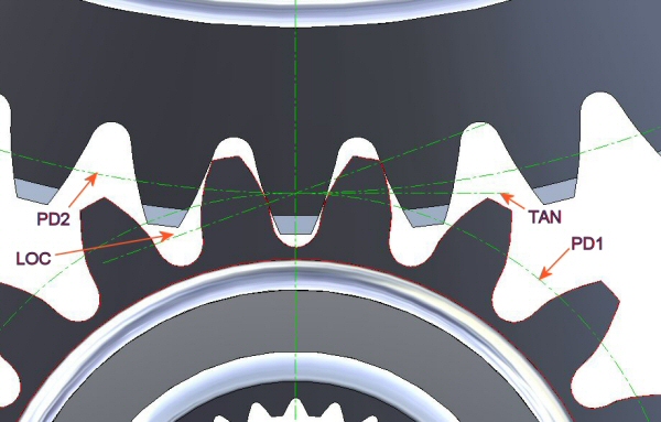
Figure 18: Contact Geometry of Spur Gears
If the load is significant, those two loaded teeth will have deflected from their unloaded (‘theoretically perfect’) positions. That deflection allows the rest of the driving gear to move slightly ahead of its theoretical undeflected position, and allows the driven gear to lag slightly behind its theoretical undeflected position. Those slight deflections cause all the unloaded teeth on both gears to move slightly out of their correct positions with respect to the tooth-pair carrying the load.
Because of that deflection, when the next tooth-pair comes into mesh, they touch each other sooner than they would if there had been no deflection, thus they pick up a disproportionate amount of the load very quickly.
That sudden load application produces a hammer-like force (impact) which can cause the teeth to bounce apart (just as a hammer will rebound from striking a hard piece of steel) then re-contact later in the mesh, causing another impact. The forces seen by the teeth during these impacts can be much greater than the load applied by the transmitted torque.
Added to that problem is the fact that it is not possible to manufacture theoretically perfect gear teeth. As the errors in tooth location and profile increase, the magnitude and randomness of the dynamic load increase as well.
The determination of the dynamic loads is a complex procedure. It takes into account factors which include gear tooth manufacturing tolerances, tooth stiffness, torsional rates of all loaded shafts and gears, and mass moment of inertia values of the engine, connecting shafts, gears and the driven load.
That dynamic load methodology is described in detail in the published works of gear technology pioneers Earle and Elliot Buckingham (Library Section 2, Volumes 11 and 12). Volume 12 includes the calculations for static and dynamic tooth bending and contact stresses, stress concentrations as a function of tooth root radius, and depth of maximum shear.
I used the methodologies from their books as the basis for a computer program that calculates those loads and stresses, and estimates fatigue life for various configurations of gear drives. That allows me to adjust various parameters in the system to reduce the dynamic-to-static load ratio (Wd / Ws) to (typically) less than 1.10.
FWIW, I have found, through many of those analysis problems, that a gearbox that has a sufficiently-soft input system to obtain the torsional-isolation results defined above will, in most cases, have a decently-low Wd / Ws ratio.
GEAR FATIGUE
Regarding fatigue life, I use the term estimate because the mathematics of FATIGUE IN METALS are largely statistical and involve the use of safety factors derived from successful field experience.
Typical heat-treated steels exhibit a property known as the endurance limit, which represents a theoretical cyclic stress level that the material can withstand for an ‘infinite’ number of cycles.
The “endurance limit” is commonly defined as the amplitude of the fully-reversing cyclic stress that the sample material can survive for 10^7 cycles.
However, the case-hardened steels that are commonly used in highly-loaded gears (carburized 8620 and 9310) do not exhibit an endurance limit. That makes long-life gear design an even greater challenge.
A gearbox which contains a single idler gear ( "two-mesh" ) requires special attention with respect to gear tooth fatigue. The teeth on the PSRU input and output gears are subjected to severe fatigue loading: zero to maximum and back to zero, every revolution. However, the teeth of a single idler which meshes with both the input and output gears are subjected to the most severe form of fatigue loading: fully-reversing load.
They are fully loaded in one direction when they mesh with the input gear and fully loaded in the opposite direction when they mesh with the output gear. In the single-idler case, the allowable working stress level is about 2/3 of the unidirectional-load value, and tooth load limits are usually established by the idler at that reduced working stress level.
That is one of the main reasons why it is essential to reduce the gearbox input waveform to as close to a flat line as possible, by reducing the transmissibility value to near-zero in the operating range.
The use of the combined technologies of isolating the gears from the engine vibration and of minimizing tooth dynamic load has enabled me to use rather small gears successfully in various propeller gearboxes. One model (the Mark-9) had a 1.5 in-wide, 6 DP, 21-tooth input gear (3.500 in pitch diameter), and could handle over 600 lb.-ft. of input torque virtually forever at very modest stress levels. One of those gearboxes raced successfully at Reno for several years, driven by a 625 HP V8 (565 lb-ft) engine.
The gears for the 1800 HP (1575 lb-ft) race version of my V12 are 2 inch-wide, 5 DP gears that implement a 3.16 ratio and have a predicted life of over 1000 hours at an input torque of 1600 lb-ft. The dynamic load ratio (max dynamic load ÷ max static load) for the driving gear is 1.027, and for the driven gear, it is 1.096.
Figure 19 shows the 12.4-inch diameter output gear for that gearbox.
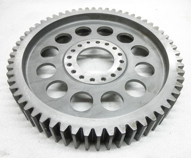
Figure 19: Output Gear for Race V12 - 1600 lb-ft Long-Life Torque Capacity
Regardless of the imagined superiority of helical gears, almost all my gearboxes use spur gears, discussed on detail HERE. That practice follows several highly successful propeller gearboxes such as the Rolls-Royce V-1650 Merlin, the Allison V-1710, most of the Pratt & Whitney radials, the Continental GTSIO-520 and -550 engines, as well as the Garrett TPE-331 and Pratt & Whitney PT-6 turbines.
Spur gears are less expensive to make, do not suffer from the edge-loading problems that arise from not having a precise match of helix angles on mating helical gears, and do not produce the considerable axial forces that helical gears generate.
I use spur gears ALMOST EXCLUSIVELY, that have a 20° pressure angle and FULL FILLET ROOTS, to achieve better bending strength, at the expense of greater gear separation force than what is produced by lower pressure angles.
I think it is ESSENTIAL to specify gear profiles that have the full-fillet-root-radius between adjacent teeth. That configuration is evident in Figure 19 above, and is illustrated in Figure 18 above. NEVER, EVER use flat-root gear teeth (or splines, for that matter). The stress concentration values that occur in very small radii are killers to fatigue life.
HELICAL GEARS
The only exception to my "spur-gear-only" rule is the occasional design in which I use an off-the-shelf automotive planetary gearset for a low-torque application such as shown HERE and HERE.
Helical gears are also quite useful to transmit a limited amount of power between shafts that have non-parallel axes, such as are used to drive the distributors and oil pumps from the camshafts in countless automotive applications. Those implementations are known as 'crossed helicals'. They offer a significant challenge in design that is different from helical gears on shafts with parallel axes.
Whereas gears on shafts having parallel axes have a theoretical line-contact between driving and driven teeth, that is not the case with non-parallel axes. Crossed helicals have a theoretical point-contact between driving and driven teeth, which applies a huge contact stress to the teeth at the point of contact, despite having relatively low applied loads.
NOTE that steel gears in a crossed-helical application do not survive well because the nature of tooth contact in a crossed helical set is POINT contact, not LINE contact as in parallel axis gearsets.
In order to survive a relatively low transmitted force value, the modulus of elasticity of the materials used in crossed helicals must be low enough (much lower than steel - approxintately 30x106) to allow elastic deformation at the point of contact, so as to increase the contact area enough to reduce the contact stress to a survivable level. I use crossed helical gears in my gearboxes to implement the governor drive mechanism, described above. I have found that a grade-30 cast iron (modulus approximately 15x106) serves very well in this application.
Other than those specialized applications, as far as I am concerned, the only virtue of helical gears is they are quieter than equivalent spur gears, but in racecars and aircraft, gear noise hardly matters.
SPLINES
In addition to gear loading, the stresses that occur in the various splined connections in a gearbox must be determined. I use fine-pitch (24/48 to 48/96), 30° involute, full-radius-fillet splines exclusively. AGAIN, DO NOT CONSIDER flat-root splines, because although the torsional stress at the root is a bit less, the stress concentration factors resulting from those tiny root radii are huge, and will significantly affect the fatigue life of the spline.
For my splined connections, I use a ONLY a Fillet-Root, Side-Fit with Class-5 Tolerances (detailed in Machinery's Handbook (Library Reference 2 : 22 : 2157-2187 ).
The peak stresses typically occur under the root of an external spline, as torsional stress. For 300-M material at 52 HRc, I limit that peak stress level to 55 ksi, and 45 ksi for 4340 at 46 HRc.
As an example, a 32/64 fillet-root spline with 40 teeth under a 720 lb-ft torque load produces a torsional stress under the root of 53.7 ksi. Shear stresses at the pitch line are somewhat less.
The detailed analysis methodology for those splines can be found in Machinery's Handbook (Library Reference 2 : 22 : 2157-2187 ). An EXCEL spreadsheet that implements the analysis defined there can be a very useful tool.
PLANETARY GEARSETS
The planetary gear approach offers some interesting possibilities including compactness, light weight, reliability derived from load-sharing, and simple support for a hydraulic constant speed propeller.
Properly designed for a specific application, the planetary approach can be very successful. Many of the big radials used planetary reductions (P&W 1830, 2000, 2800, 4360; Wright 1820, etc) and one of the geared Lycoming 480 engines uses a planetary reduction.
Using a planetary approach maintains the propeller centerline coincident with the crankshaft centerline. That is desirable for a radial, a rotary, or an opposed engine, but not so much for a "V" or inline engine configuration.
In an engine conversion, to maintain the existing thrust line placement, a "V" engine with the prop on the crankshaft centerline would have to be be raised, creating an ugly cowling exercise (unless you are willing to invert the engine). Alternatively the thrust line could be lowered, but reducing the distance between the thrustline and the aircraft CG is destabilizing (Library_Reference_4_:_8, Perkins & Hage, Airplane Performance, Stability and Control), so it’s typically not a good approach for a "V" or inline engine retrofit.
The automotive origins of most of the current planetary PSRU’s limit them to relatively low-power aircraft applications. However, certain vendors are building their own planet carriers which provide more planet gears than the automotive configuration. That looks like a good step toward higher power applications.
There is an extensive discussion of planetary gearsets and the limitations imposed on various configurations, with special emphasis on the adaptation of automotive planetaries for use in geared reduction applications presented on THIS PAGE.
BELT DRIVES
Belt drives (both V-belts and toothbelts) have been used in various aircraft drive systems. The helicopter in which I got my rotorcraft rating (Hughes 300) used a matched set of 6 (or maybe 8) V-belts to connect the Lycoming HIO-360 to the drive system, and a mechanically-actuated idler / tensioner to provide the drive clutch function. It seemed to work very well.
There have been applications of toothbelt drives for PSRU's and for other helicopter drive systems.
HOWEVER, the use of belts provides some interesting challenges, ESPECIALLY with regard to high-strength toothbelts. THIS ARTICLE presents a fairly detailed explanation of the issues and challenges presented by belt drives.
HY-VO CHAIN REDUCTIONS
We have used Hy-Vo™ chain drives in several successful industrial transmission situations as well as several helicopter gearboxes. They work well in those applications because (a) the loading is appropriate for the capacity of the chain used, and b) the distance between input and output shafts is large enough that a geared solution would be prohibitively heavy or expensive (or both). There is a complete treatment of HyVo chain usage on THIS PAGE. Below, I have listed the high points.
There are two primary failure modes with a link-chain drive.
The first is a progressive failure which results from an apparent elongation of the chain due to wear in the link-pin joint. Failure occurs when the apparent chain elongation has reached the point that the chain begins to skip teeth. Catastrophic failure is not far behind that event.
The second, and more critical failure mode, is a catastrophic breakage of the chain due to tensile fatigue loading of the sideplates. This failure is sudden, complete, and potentially explosive.
HY-VO CHAIN LOADS
Let's examine the two sources of chain load.
The first is APPLIED TORQUE. Torque from the engine is applied to the driving sprocket. That torque produces a tension force in the tight side of the chain which is equal to the applied torque (lb-in) divided by the pitch radius of the sprocket (same as the TANGENTIAL FORCE on a gear). The chain transmits that tension force onto the driven sprocket, and that tension force applies a torque to the output shaft, the value of which is the input torque multiplied by the ratio of the pitch diameters - - OR the tooth-count ratio (Driven Sprocket TC ÷ DRIVER SPROCKET TC).
The second source of chain tensile loading is CENTRIFUGAL FORCE. That force results from the chain traveling in a circular direction around the two sprockets, and produces a tension force which is equal throughout the entire length of chain. That force is proportional to the weight of the chain and to the square of the pitchline velocity.
The centrifugal force adds to the driving tension force on the tight side of the chain. On the slack side, the chain is still carrying the tensile force generated by the chain centrifugal action. Therefore, with a constant torque applied to the drive, the cyclic loading on a given link varies once per full travel cycle around both sprockets, from the high tensile load (driving-plus-centrifugal on the tight side) to the low tensile load (centrifugal-only on the loose side) and back to the high tensile load. If the magnitude of that varying load is too high, the side links of the chain will fracture from fatigue cycling (explained fully HERE).
In the Morse Hy-Vo chain tables, you will notice that the power rating of a given chain will increase as RPM increases, at a fairly linear rate UP TO A CERTAIN RPM, and then the rate tapers off substantially until the power increase with RPM becomes very small. That is because of the ever-increasing tensile load that results from the centrifugal force of the whirling chain, which adds to the tension load being applied by the driving sprocket.
Chains of a specific pitch are rated by horsepower capacity per inch of width for DIFFERENT DIAMETER DRIVING SPROCKETS and for DIFFERENT RPM. That rating method is a simplified way to take into account the fact that there are two different sources of tensile loading in the chain: (a) applied torque and (b) centrifugal force from rotational speed. The rated horsepower number in the Morse HyVo chain tables combines those parameters. The power capacities listed in the HyVo design tables are the maximum for which Morse Engineering have determined the chain can provide "infinite life" when their application-specific limitations are observed.
The engineering people who designed the Hy-Vo chain, based on millions of hours of real-life experience with all kinds of driving machinery (gasoline engines, diesel engines, electric motors, turbine motors, etc. etc.) and all kinds of driven machinery (reciprocating pumps, centrifugal compressors, propellers, generators, machine tools, etc), have determined the values of fatigue loading which a specific chain, in a specific application (Power loading, RPM, Driving torque fluctuations, Driven load characteristics, Start / stop characteristics, and more) can survive for 2.5 million cycles. If the chain can survive that number of cycles at that specific fatigue loading, the chain is considered to have " infinite life ".
HOWEVER, if the chain is subjected to the raw torsional pulsing of the engine (ie, connected to the PSRU by something OTHER than an effective torsional isolation system), the expected life will be much lower.
Those catalog and calculation-specific life values are based on the fatigue strength of the outer links. As explained on THIS PAGE, the endurance limit of a material is a statistical value, based on apparently-identical polished specimens, tested at various fully-reversing bending stress levels in a laboratory. But the real-life application of an EL has to be based on adjustments to a value known as the Application-Specific-Endurance-Limit, explained HERE.
HY-VO BEARING LOADS
It has been claimed that a chain drive is better than a gear drive because it eliminates the shaft bearing loads from the separation force which gears generate. Although the elimination of gear-separation loading is technically true, the reality is that in a chain drive, the gear separation force pushing the shafts apart is replaced by a similar force which is pulling the two shafts together, approximately equal to the sum of the driving tension plus twice the centrifugal force. That force increases with chain speed, and can become very large. It is applied to the bearings on both shafts.
HY-VO COOLING
Component temperature is an important consideration in chain drives. The manufacturer specifies a maximum of 250°F for the chain in order to stay safely away from the tempering temperature. If that temperature is reached, the tensile strength and fatigue life of the chain will be significantly reduced, as will the life expectancy of any rolling element bearings. (see LUBRICATION AND COOLING).
HY-VO VIBRATION PROPERTIES
An interesting property of a Hy-Vo chain is the elastic elongation (stretch) which the chain experiences in response to a load. This stretch-per-unit-load (aka "spring rate") inserts an apparent torsional rate into the system, and somewhat reduces the first mode resonant frequency of the system.
Typical torsional rates for a 2:1 reduction ratio implemented with 2.0, 3.0, or 4.0-inch wide chain are roughly 266, 328 and 375 lb-ft per degree respectively. (That rate VARIES with the tooth count of both sprockets, the chain width and the distance from the input shaft to the propshaft.)
HOWEVER, this chain rate does NOT alter the pulse transmission characteristics of the ENGINE-TO-DRIVEGEAR coupling. If the transmissibility of the ENGINE-TO-DRIVEGEAR coupling is not low enough, the engine pulses are still applied to the driving sprocket and then to the chain, and might very well be amplified (see TRANSMISSIBILITY) depending on the system characteristics.
The torsional chain rate MIGHT or MIGHT NOT diminish the pulse amplitude applied to the output shaft and the propeller, depending on the masses and spring rates of the other components of the system.
HY-VO "SELF DAMPING" ???
We have heard several purveyors describe their link-chain drive as being "self-damping". Let’s discuss these alleged "self-damping" characteristics.
First, recall the discussion of VIBRATION BASICS, where damping was defined as the property of energy dissipation. The dissipation of feedback energy from a system near resonance has the effect of limiting the vibration amplitude from going totally out of control. Recall (from the discussion of transmissibility earlier in this article) that, no matter how much (real) damping there is in a system, at resonance, there will still be amplification of the excitation forces.
Various marketeers of Hy-Vo PSRU drives claim that, because the slack side of the chain is loaded only by the centrifugal-tension force, somehow that magically introduces "damping" into the system. All it really introduces is backlash, which increases as the chain stretches through wear.
There can be an argument made that resonant vibration is less likely to go out of control because, near resonance, the entities being driven by the chain (prop and propshaft) have a difficult time feeding energy back into the vibrating system, due to the large amount of effective backlash. That effect is probably what is being incorrectly hyped as "self-damping".
GEARBOX BEARINGS AND LUBRICATION
All the bearings in my single-mesh propeller gearboxes are pressure-fed hydrodynamic bearings (the input and output shafts and the propeller bidirectional thrust bearings). That allows a very high level of load capacity without the large size and weight penalties that would result from rolling element bearings having similar capacities. For example, the Mark-15 gearbox hydrodynamic thrust bearings can easily accommodate thrust forces in excess of 3000 lb in either direction.
In my two-mesh systems, the input, output, and thrust bearings use the same hydrodynamic bearings designs, but for the idler shaft, it is sometimes easier to use rolling element bearings. For those applications, I use spherical roller bearings whenever possible because of their huge combined radial AND thrust load capacities. A relatively small pair of spherical-rollers can sustain a large loading with demonstrated infinite life.
The properties and calculation methods for rolling element bearings is detailed HERE.
In almost all cases, my gearbox lubrication / cooling system uses pressurized, filtered and cooled engine oil. That has been proven to be effective for decades, going back to the original Mini Cooper with the crosswise engine that had the gearbox in the crankcase. It has also proven to be effective with several different versions of my gearboxes, with the added advantage of reducing cooling drag by relying on only one heat exchanger for the cooling of all the oil in the propulsion system.
Pressurized oil is fed to the bearings through internal galleries in the housing set, and is strategically directed at the exiting-mesh area of the gear teeth by jets, coupled with copious splash lubrication from the hydrodynamic bearing run-off. With engines having an external oil pump system, a dedicated section of the engine oil pump scavenges the gearbox oil and returns it to the oil tank or crankcase as applicable. In cases where the engine oil pump is internal AND has sufficient capacity, I add an external scavenge pump to the front of the gearbox, which returns gearbox oil to the crankcase.
Be advised that gravity-return of the gearbox oil (in all the cases I have worked with) will not work. Try pouring 3-4 gallons-per-minute of ATF through a 3/4" ID hose.......
PROPSHAFT
As discussed in the torsional isolation section, the input shafts, because of their design to achieve low torsional rates, operate at cyclic torsional stress levels that are quite high (often up to 55 ksi). Those stress issues are covered during the design of the isolation system.
The propeller shaft carries very large loads that include:
- the torque applied by the engine, multiplied by the gear ratio,
- the bending forces applied by the gear separation loads,
- the thrust forces applied by the propeller, in both directions (the rearward thrust can be as much as the propulsive thrust during power-off dives, for example),
- the cyclic bending moment applied by the overhung weight of the propeller, especially when subjected to airframe g-loading,
- and the often very-large bending loads applied by the gyroscopic force the propeller generates during any pitch or yaw events.
So it should be obvious that the peak values of these various loads must be calculated, then applied to the propshaft, ideally with an FEA software package.
The results of that analysis will also produce the resultant loads that the shaft applies to its bearings. Those loads are needed for the housing design process.
For certificated aircraft, the Federal Aviation Regulations provide a comprehensive set of design criteria. These minimums, provided in 23.361 (engine torque effects) and 23.371 (combinations of gyroscopic and aerodynamic loads) provide good guidance for experimental designers as well.
Figure 16 shows the FEA of the Mark-15 propeller shaft with 4980 lb-ft of propeller torque, 3000 pounds of thrust, 2900 lb-ft of propeller gyroscopic moment (that's NOT a typo), and 3626 lb of gear separation load applied. The results show a peak stress of 101,000 psi in the fillet just behind the prop flange, which is suitably below the material endurance limit.
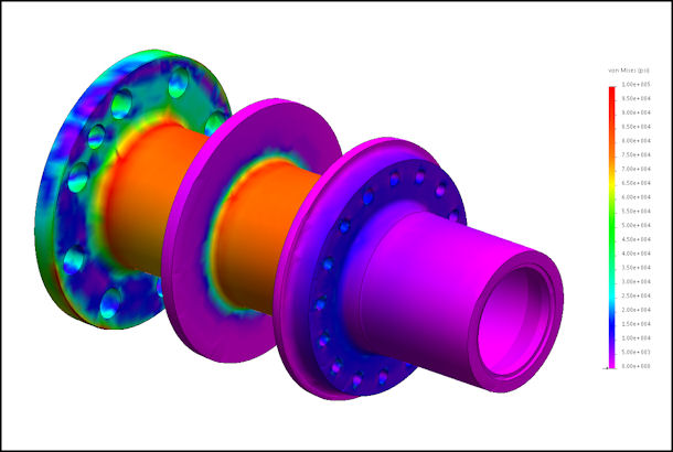
Figure 16: FEA of Propeller Shaft Under Combined Large Loads
HOUSINGS
Having resolved all the design issues discussed up to this point, it is now necessary to design a housing set that has sufficient strength AND stiffness to support all the loads that will be applied, including: (a) torsional loads, (b) thrust loads, (c) "g"-loads, (d) gyroscopic loads, and (e) applied bearing loads.
HOUSING LOADS
FAR 23.371 (again, not required for EXP, but nevertheless a good source of design parameters) requires that an engine mount structure be proven to carry, without permanent deformation, the loads applied by the worst-possible combination of:
- a yaw velocity of 2.5 radians per second,
- a pitch velocity of 1.0 radian per second,
- a downward vertical load of 2.5 g, and
- maximum continuous thrust at 1.25 times the engine torque at maximum continuous power.
Now, consider the fact that, in addition to the INTERNAL loads generated by the power transmission mechanism (gears, chains, belts, whatever), the combined EXTERNAL loads mentioned above must be carried by the PSRU housing.
Here is an example:
- 2.5 rps yaw with a common metal prop at 2500 RPM applies over 2250 lb-ft of torque to the propeller flange in the pitch direction..... a 106" metal 3-blade prop at 1900 RPM, such as used on our cropduster conversion, applies nearly 3250 lb-ft to the flange.
- 1.0 rps pitch with a common metal prop at 2500 RPM applies nearly 915 lb-ft of torque to the propeller flange in the yaw direction;
- 2.5 times the weight of the PSRU plus Propeller, plus approximately half of the engine weight can amount to well over 1000 pounds of "g-load";
- anywhere from 800 to 3000 pounds of thrust, plus the PROPELLER torque (gear ratio times engine torque).
The bearing supports in the housing must be capable of carrying all the loads applied by the various shafts. But the housing must also be capable of transmitting the combined loads to (a) the engine and (b) the mount structure without unacceptable levels of BOTH STRESS and DEFLECTION.
The Mark-15 Single-Mesh gearbox housing system shown below (Figure 20) consists of three sections: (a) the front gear housing, (b) the rear gear housing, and (c) the bellhousing section, that can be configured to attach to a wide variety of engines. All three sections are CNC-manufactured from high-strength aluminum billet material. The system has been designed to provide the strength and stiffness required by the combination of propeller torque loads, gear separation loads, thrust loads, g-loads, and the large gyroscopic moments that result from rapid changes in angular velocity in the pitch or yaw axes.
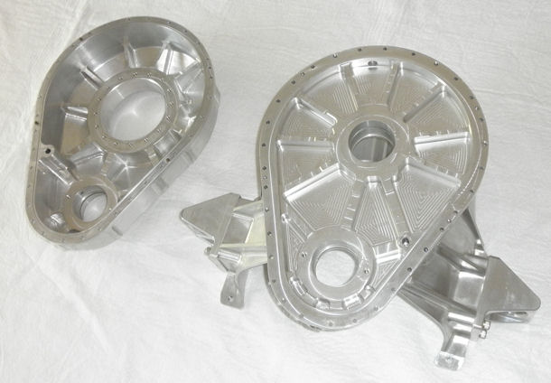
Figure 20: Propeller Gearbox Housing Set - CNC from High Strength Aluminum Billet
Extensive FEA work on the housing set has helped achieve the targeted very low deflection characteristics, which yielded relatively low stress values, even at extreme conditions.
Figure 21 shows the stress FEA of the housing set with 1600 lb.-ft. of applied input torque, 5056 lb-ft of opposing propeller drive torque, 3626 lbs of gear separation load on each shaft, 3000 lbs of thrust, 2900 lb.-ft. of propeller gyroscopic moment, and the mount loads resulting from a 3g vertical acceleration on the entire airframe. The results show a peak stress of 11,000 psi and a peak deflection of less than 0.003 in (in the mounting ears).
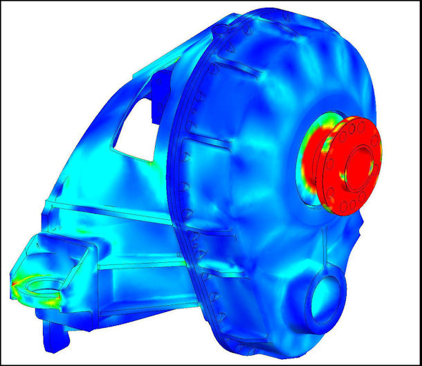
Figure 21: FEA of Housing Set under Combined Large Loads
THE PICTURE BELOW shows the test fixture, designed and built by a client, to test his 650 HP supercharged BMW M73 V-12 engine with the first single-mesh Mark 15 PSRU. This fixture can go from "straight-and-level" to fully inverted (to test the fully-inverted oil system) and from 45° pitch-up to 45° pitch-down.
CLICK ON THE PICTURE to see a video showing the first run of the single-mesh Mark-15
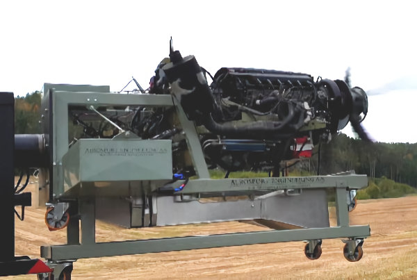
Figure 22: Powerplant Testing Movie
CONCLUSIONS
Hopefully this article will provide some guidance and assistance to those who wish to design their own PSRU. It can also provide some insight that could be helpful in evaluating a PSRU being considered for purchase.
Following is a summary of some key points that I hope have been made here.
(1) This is perhaps THE most important point of this entire discussion:
PSRU’s, propellers, engine conversions, and engine mounts are COMPLEX devices. PSRU’s are the incarnation of EXPERIMENTAL. There is no significant body of accumulated experience behind most of them, and many of them have a disturbing history of fatal experiences. Treat them as such.
(2) Understand the complexity of your project.
The life expectancy of your PSRU and propeller (and by extension, you, your passengers and your aircraft) depends on a complex mixture of factors including the dimensions, stiffnesses, materials, heat-treatments, and quality control of critical components, the metallurgical goodness of the gear material (AGMA GRADE), the accuracy (AGMA QUALITY) of the gears, the reduction ratio, the Jm (mass moment of inertia) of the propeller, the talent of the designer(s), and other factors.
(3) TEST STAND OPERATION IS NOT THE SAME AS FLIGHT.
That fact has been demonstrated far too many times in real life.
(4) DO NOT be misled by the often-quoted-yet VERY FALSE belief that "if you cannot FEEL vibration, then none exists".
The reality is that destructive vibration can (and often DOES) occur at frequencies that are far beyond the range that humans can detect. You are free to believe whatever you like, but that belief doesn't change the facts.
(5) Be SUSPICIOUS of:
- any PSRU that allows the use of a light flywheel,
- any PSRU that has a torsionally-rigid coupling between the engine crankshaft and the PSRU drive gear, or
- any PSRU that which can be bought without a drive coupling system engineered for THAT PSRU and YOUR engine.
(6) RUN (don’t walk) away from anything with an alleged vibration-killing one-way clutch in the propeller drive system, or with magical-sounding (but unexplainable) properties.
Be careful and be cynical.
(7) Ask Hard Questions.
Before buying a PSRU, have the seller satisfy you (with data, not allegations) that the SYSTEM will operate correctly with your selection of engine, propeller, and gear ratio. Don’t be satisfied with marketing drivel.
(8) TBO CLAIMS !
Remember that, unlike the experimental world, TBO numbers in the real world are established on the basis of substantial experience and documented evidence, both practical and scientific. Far too many TBO's in experimental aviation are no more than the product of some peddler's wishful thinking.
(9) Ask to talk to the designer.
Don’t be afraid to ask him the relevant questions (see FAQ's). Maybe the designer knows about gears but didn’t do the vibration analysis. Maybe the designer has no engineering knowledge at all, but has money enough to buy CAD software and CNC machining equipment, and can talk faster than you. Maybe the "...thousand hours this PSRU has in service" came from 10 hours each on 100 airboats. Ask about previous litigations involving their products. Speak to actual customers.
(10) Don’t accept one of the countless variations on the following theme:
THIS PRODUCT WAS DESIGNED BY THE (best, most experienced, most aviation-knowledgeable) EXPERT IN (the world, the USA, Arkansas, Cleveland) BUT HE (is too busy, is undercover for the CIA, has been abducted by aliens, only speaks Swahili) AND CAN’T TALK TO YOU.
(11)Be cautious of most race-car experts.
There are a FEW brilliant race-engine guys out there, but they work in NASCAR / INDYCAR / F1 shops and you can't get at them. Keep in mind that a race-car-guy's perspective is often quite different than yours in terms of longevity. The purpose of a race engine is to deliver the most power possible within the rules structure, and to survive at that output level / RPM only as long as the end of the race. "Long Life" for a race engine is all relative. For a NASCAR CUP, Xfinity, or Camping World engine, long life is 5-7 hours. Long life for a typical hi-performance ski-boat engine is around 100 hours. Long life for a dirt sprint car engine is around 10 hours. ( Some race-car-guys think long engine life is 15 seconds, measured in 5-second chunks.)
REMEMBER: Lots and lots of Lycomings and Continentals live thousands of hours at 75% power without a failure. In fact, a great deal of the grief with "LycoNentals" comes from DISUSE.
(12) FAR's Don't Apply.....?
While it is well recognized that the Federal Aviation Regulations defining design and testing standards (PARTS 23, 33 & 35) do not apply to experimental aircraft, nevertheless those regulations provide a rich source of MINIMUM DESIGN STANDARDS which a prudent aircraft designer would be well advised to study, especially with regard to structural and reliability issues.
