
- Gear Design -
Geometry, Power Ratings, Dynamic Loads, Fatigue
NOTE: All our Products, Designs, and Services are SUSTAINABLE, ORGANIC, GLUTEN-FREE, CONTAIN NO GMO's, and will not upset anyone's precious FEELINGS or delicate SENSIBILITIES.
This section contains information on several important topics with respect to the properties of gears and the loads imposed on them in a geared transmission system. It will be worthwhile to take the time to read through the four main topice on this page if you are truly interested in knowing how a geared system functions.
CONTENTS
Introduction to Gears
This section explains the meaning of a few basic gear terms, including ratio, pitch diameter, diametral pitch, pressure angle, line of contact, involute profile, tangential force and separation force.
The purpose of gears is to transmit uniform rotary motion from one shaft to another, and usually to turn the driven shaft at a different speed than the driving shaft.
The difference between input and output speed is known as the RATIO, and can be calculated by:
RATIO = OUTPUT SPEED ÷ INPUT SPEED,
or by
RATIO = OUTPUT GEAR TOOTH COUNT ÷ INPUT GEAR TOOTH COUNT
or by
RATIO = OUTPUT GEAR PITCH DIAMETER ÷ INPUT GEAR PITCH DIAMETER.
Pitch diameter and other gear terms are explained below.
The following discussion about transmitted power and torque presumes zero losses in the gears, meshes and bearings, or 100% efficiency. Clearly that is not the case in real world gears, and there is always some power lost to friction whenever a gearbox is operating, and with some types of gearing, those frictional losses can be substantial.
Whenever the ratio is other than 1-to-1, the output torque will be different from the input torque by the inverse of the ratio. For example, consider a pair of gears in which the driving gear has 21 teeth and the driven gear has 48 teeth. The ratio would be 0.4375 (21/48). If the input shaft was turning at 5000 RPM, the output shaft would turn at 2187.5 RPM (5000 x 0.4375 = 2187.5). If the input torque was 500 lb-ft, the output torque would be 1142.8 lb-ft (500 ÷ 0.4375 = 1142.8), and the output power (1142.8 lb-ft x 2187.5 rpm / 5252 = 476 HP) is the same (ignoring gearbox losses) as the input power (500 lb-ft x 5000 rpm / 5252 = 476 HP).
If you are unclear about POWER and TORQUE, please divert to THIS ARTICLE and then come back here.
Basic Gear Terminology
Imagine two circular wheels in contact with each other at their outside diameters, with one wheel turning at a constant speed, and driving the other wheel by friction, with no slippage between the mating surfaces. The motion imparted to the driven wheel would be uniform rotary motion.
Two accurately manufactured gears in mesh behave like the two circular wheels described above. Gear teeth in mesh with each other operate as if they were two cams which have profiles specifically developed to implement the required uniform rotary motion, while being a ble to transmit much greater forces than would be possible by friction contact between two wheels.
The profile which accomplishes that transmission of uniform rotary motion is a mathematical function known as an involute. The nature of an involute profile is such that at any point from the beginning of mesh to the end of mesh, the contact point of the two tooth faces lies along a straight line , called the Line Of Contact.
The animation below shows this meshing of involute gear teeth. Note how the point of contact between the teeth is always located along the Line Of Contact (the solid orange line). The pitch diameters of the gears are the dotted orange lines and are tangent where they intersect the line of contact. Also, if you watch the animation closely, you will see that, contrary to popular mythology, the relative motion between two contacting involute gear teeth is SLIDING motion at all points of contact EXCEPT where the two pitch diameters intersect. These relationships are exaplained further in the following text and pictures.
(NOTE: The animation above was kindly provided by Camnetics, Incorporated, makers of several excellent gear and cam design software programs which can act as add-ins for SolidWorks, Inventor, Solid Edge, and other 3D-CAD packages.)
The pitch diameter of each gear is the outside diameter of its effective circular wheel. The two pitch circles touch at a point on the straight line between the two gear centers (the vertical green line in the picture below). That contact point is the point at which the two pitch diameters are tangent to each other.
The pitch circles of the two gears pictured below are marked PD1 and PD2 respectively, and touch each other at the point of tangency. The (vertical) centerline connects the center point of each gear. The point of tangency lies at the intersection of the centerline and the two pitch circles. The horizontal line marked TAN is perpendicular to the centerline and passes through the point of tangency. The Line Of Contact, marked LOC, shows the contact points of the teeth from the beginning to the end of mesh.
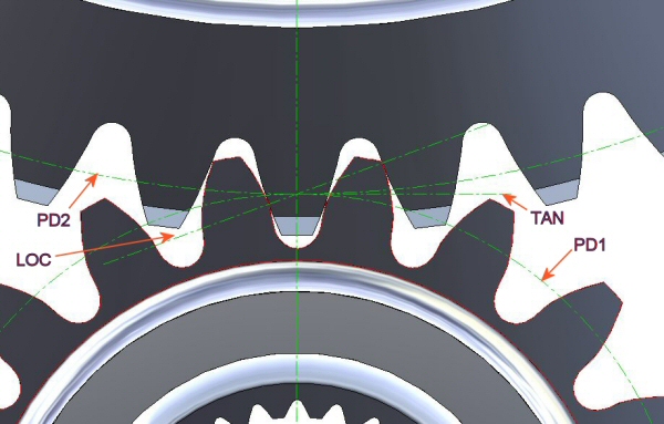
Because the involute profile maintains the contact point along the LOC, the effective contact point between the two gears remains at the point of pitch-circle tangency. That causes the motion imparted to the driven gear to be uniform angular motion.
The tangent line (marked TAN) is a line tangent to both pitch diameters (hence perpendicular to the straight line between the centers of the two gears). The gear's pressure angle (PA) is the angle between the tangent (TAN) line and the line of contact (LOC). Meshing gears must have the same pressure angle.
The force which the tooth on the driving gear applies to its mating tooth on the driven gear is applied along the line of contact (LOC), and is known as the normal force (perpendicular to the tooth surface). Look at the picture closely and you can see TWO PAIRS of teeth in contact, and both points of contact are on the LOC.
The normal force (the force along the LOC) which the driving gear applies to the driven gear at the point of contact is generally handled as two perpendicular components: (a) the tangential force (horizontal in the picture), and (b) the separation force (vertical in the picture).
The tangential force (tangent to BOTH pitch diameters) is applied by the driving gear along the line marked TAN. The value of the tangential force is the input torque divided by the pitch radius (half the pitch diameter).
The separation force is applied along the centerline between the centers of the two gears, and is trying to drive the two gears apart from each other.
The relationship between tangential and separation forces is determined by the pressure angle (PA) of the gears. From simple trigonometry and the picture above, it is clear that the normal force is the tangential force divided by the cosine of the pressure angle, and the separation force is the tangential force times the tangent of the pressure angle.
The term diametral pitch (DP) describes gear tooth size, and is defined as "the number of teeth per inch of pitch diameter".
As an example, consider a 6-DP gear with 21 teeth. That gear has a pitch diameter of 3.5 inches (21 ÷ 6 = 3.5). Now picture that 21-tooth gear meshed with a 6-DP, 47 tooth gear.
The 21-tooth gear has a mean torque of 625 lb.-ft. applied to it. The force tangential to the pitch circle is 4286 pounds, determined as follows:
Tangential Force = (625 lb-ft x 12 inches per foot) ÷ (3.5 inches ÷ 2)
Tangential Force = 7500 ÷ 1.75 = 4286 lbs.
Once the tangential force is known, the normal and separation forces can be determined, as follows:
The separation force is 4286 x TANGENT (20°) = 4286 x .364 = 1560 lbs.
The normal force is 4286 ÷ COSINE (20°) = 4286 ÷ 0.94 = 4560 lbs.
These forces (tangential and separation) must be counteracted by the bearings which support the gear shafts.
These loads are sometimes referred to as "static" gear loads, because they can be generated by statically loading the input shaft at the specified input torque, without any motion being imparted to the gears.
Static loads are only one part of the whole picture to be considered, as explained in the section below on Dynamic Loads.
Back to top
Power Ratings
PSRU sellers often advertise the horsepower that their unit is claimed to handle. Such a claim suggests a lack of understanding about the basics of power transmission. The power which is transmitted through a gearbox is only of interest for determining heat rejection (cooling) requirements (and apparently for advertising hype), but is essentially meaningless in terms of the loads applied to the internal components.
Why? Because, as you know, TORQUE is the measure of the actual FORCE a rotating engine applies to its load. POWER is simply a mathematical expression of WORK-PER-UNIT-TIME (see Torque and Horsepower).
The TORQUE applied to the first driving gear in a gearbox is the value which determines the force which is applied to the faces of all other gears in a geartrain, as explained above in Introduction to Gears.
Consider the following example.
Suppose a certain engine produces a maximum POWER of 460 HP at 4800 RPM, and the engine's torque peak is 625 lb-ft. at 3800 RPM. Also suppose that the engine is equipped with a PSRU which was designed for the peak engine power (460 HP at 4800 RPM). Because the engine torque at maximum power is only 503 lb-ft, ( 460 x 5252 ÷ 4800 = 503) that PSRU would only be able to handle 75% of the engine's maximum torque (625 lb-ft) which occurs fairly close to the cruise operating RPM.
From the applied loads, the designer calculates static gear-tooth stresses: (a) the bending (tensile and compressive) stresses at the root of the tooth, and (b) the contact stress at the line across the tooth face where the teeth contact each other.
Because no piece of machinery is exactly perfect, provisions must be made for the fact that, due to tiny manufacturing inaccuracies, the contact force between two gear teeth will not be evenly applied across the entire face width of the tooth. In fact, this problem, known as edge-loading, can destroy a pair of otherwise-sufficient gears in a very short time. Therefore, special provisions must be made in the design of the gears to prevent edge-loading.
Back to top
Dynamic Gear Tooth Loads
An aspect of gear loading which is commonly ignored, but critically important, is the phenomenon known as dynamic load. This load occurs when a pair of teeth is just coming into mesh. Assume for the moment that we have a pair of gears which have been manufactured so accurately that the location of every tooth is absolutely perfect and the profile of each tooth is absolutely perfect. With such perfection, one might think that each successive tooth pair would pick up the load perfectly smoothly as the teeth enter the mesh. Not so, however.
Remember that metal objects have elasticity, or springiness. Visualize the tooth-mesh when a single pair of teeth is carrying all the load. If the load is significant, those teeth have deflected from their unloaded ("theoretically perfect") positions. That deflection allows the rest of the driving gear to move slightly ahead of its theoretical undeflected position and the rest of the driven gear to lag slightly behind its theoretical undeflected position. Those deflections allow the driving gear to move slightly ahead of its theoretically correct angular position, and the driven gear to lag slightly behind its theoretically correct angular position. Those slight deflections cause all the unloaded teeth on both gears to move slightly out of their correct positions with respect to the tooth-pair carrying the load.
Because of that deflection, when the next tooth-pair comes into mesh, they touch each other sooner than they would if there were no deflection, thus they pick up a disproportionate amount of the load very quickly. That sudden load application produces a hammer-like force (impact) which can cause the teeth to bounce apart (just as a hammer will rebound from striking a hard piece of steel) then re-contact later in the mesh, causing another impact. The forces seen by the teeth during these impacts can be significantly greater than the load applied by the transmitted torque.
Now we add another dash of reality. It is not possible to manufacture perfect gears.
The AGMA Quality Number is a measure of the accuracy of the tooth locations and the tooth profiles. A gear with a lower Quality Number has greater errors in tooth location and tooth profile. As the errors in tooth location and profile increase, the magnitude of the dynamic loads increase as well.
The determination of the dynamic loads is a complex methodology. It takes into account factors which include gear tooth manufacturing tolerances, tooth stiffness, torsional rates of all loaded shafts and gears, and Jm values of the engine, propeller, shafts, and gears. That methodology, which includes the calculations for tooth bending stresses, contact stresses, stress concentrations as a function of tooth root radius, and depth of maximum shear, is implemented in a computer program which EPI developed for analyzing PSRU gear systems, based on the published works of Earle and Elliot Buckingham.
Back to top
Fatigue Loads
Having determined the stress levels and the properties of the material selected for the gears, the designer can estimate the fatigue life in the load model. The term estimate is used because the mathematics of fatigue are largely statistical and involve the use of safety factors derived from successful field experience (see Fatigue). In addition, case-hardened materials commonly used in highly-loaded gears (carburized 8620 and 9310) do not exhibit infinite life at bending stress levels suitable for 10 million load cycles (the point at which many designers expect infinite life).
Another critical fatigue issue is the use of an idler gear between the driving and driven gears. This arrangement is often used to make the output shaft rotate in the same direction as the input. If the same gear in the idler mechanism contacts both driving and driven gears, its teeth are subjected to the most severe kind of fatigue loading: fully-reversing loads. The idler teeth are loaded first in one direction by the driving gear, then in the opposite direction (with the same force) by the driven gear. If the dynamic loading characteristics of each mesh are the same (unlikely) then the loads will be equal and opposite. If the dynamic loading characteristics differ, then the loads will differ, sometimes significantly. Nevertheless, those loading characteristics must be determined and the design of the idler gear must implement a suitably lower endurance load limit.
Bottom line: the designer must determine the allowable working stress levels after taking into account a large number of loading, life, and metallurgy factors. Then the gears must be designed so that the working stress levels at the intended loadings are within those limits. (Note: at 4600 input RPM, it takes only 36 hours for the driving gear to reach 10 million fatigue cycles.)
