- Mark-18 -
Helicopter Main Rotor Drive Gearbox
NOTE: All our Products, Designs, and Services are SUSTAINABLE, ORGANIC, GLUTEN-FREE, CONTAIN NO GMO's, and will not upset anyone's precious FEELINGS or delicate SENSIBILITIES.
INTRODUCTORY NOTE
STATUS: The ownership of and all rights to this gearbox (and the Mark-17 as well) have been acquired by APACHE TURBINES to provide the powerplant basis for a new helicopter product currently in development. It is NOT available from EPI, Inc, and this page continues to exist solely for informational purposes.
The Mark-18, together with the Mark-17 Power Unit Gearbox, was intended to provide a bolt-in system to replace the notorious 4-cylinder piston engine and drive system in the RotorWay Exec series of 2-place helicopters with a reliable 150-shp turbine engine system.
The Mark-18 gearbox is a separate, specially-designed 90° gearbox for the helicopter main rotor drive. It is NOT adapted from racecar parts. It bolts directly to the existing main rotor shaft and to the existing airframe components, and replaces the lower bearing on the main rotor shaft. It has an optional main rotor brake.
The main rotor drive begins with a truck-service hypoid gearset, shown in Figure 1, which is rated by the gear manufacturer for a continuous input torque of nearly 400 lb-ft. In racecar applications, we have seen these gears carry over 2200 lb-ft. of torque.
We frequently hear gearbox vendors discussing claims about the horsepower rating of their gears. That should raise a red flag for the customer, because it is a completely meaningless claim. Gears are rated for TORQUE capacity ( see the explanation here). To claim that a set of gears "can carry 800 HP in a racecar", while perhaps being literally correct, displays an unfortunate ignorance of engineering reality as it relates to the expected life of parts in service. In fact, the main rotor transmissions with the "800 HP gears" have failed in flight under less than 145 HP.
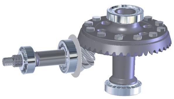
Figure 1
At max power (145 HP to the main rotor), the input to the main rotor drive from the EPI Power Unit is about 300 lb-ft, and at a typical cruise (95 HP to the main rotor) it is about 197 lb.-ft. That provides a safety margin above the continuous rating of more than 1.33 at max power and over 2.0 at cruise, so the gears should be extremely reliable. Furthermore, the ring gear is mounted ABOVE the driving pinion, in order to minimize the risk of the drive being jammed by debris. (Regarding main rotor components, we think that overkill is just enough.)
Next (Figure 2), we add our purpose-designed drive yoke, oil seals, and our main-rotor-shaft adapter system.
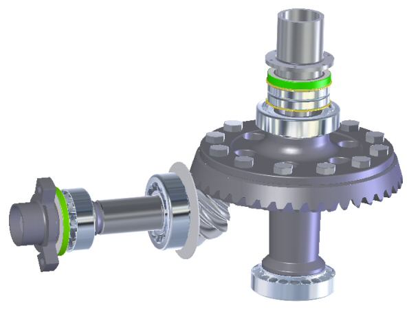
Figure 2
Around this robust hardware, we wrap (Figure 3) our purpose-designed housing system. This 4-piece system is designed for stiffness and light weight, as well as optimal lubrication and heat rejection.
Our hypoid gearset has a relatively small pinion offset distance, which reduces the severity of the hypoid angle and provides relatively low tooth-face slip-velocity (as compared to the famous Ford 9-inch, for example). That feature reduces frictional losses, and consequently, reduces the heat generated in operation.
However, there is still considerably more tooth-face slipping motion than occurs in spur and helical gears. That slipping action generates a significant amount of heat, and requires special lubricant properties ("rear-end lube").
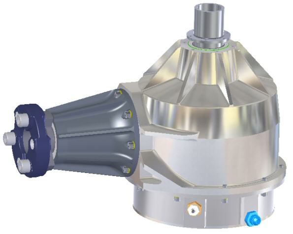
Figure 3
Therefore, our Mark-18 uses Hypoid gear lube, contained in its own separate lube oil reservoir (with screw-in dipstick and chip detector). There is a chamber below the oil reservoir which is specifically designed to act as a heat exchanger. Engine oil, just after exiting the oil cooler, is pumped through this chamber and back to the engine in order use a single air-fluid heat exchanger to remove all the system heat. The AN fitting shown in Figure 3 nest to the chip detector, is the inlet for cooling oil.
Lastly, we add the (optional) main rotor brake system, shown in Figure 4. This system is capable of stopping the main rotor in less than 10 seconds (after the startup clutch is disengaged, of course ! ) and is operated by a hand control in the cockpit.
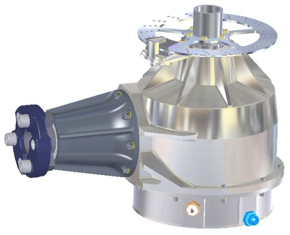
Figure 4
Note that the airframe-attachment points are not shown in these pictures. They will be defined when the target airframe design is complete.
