- Mark-17 -
Turbine Helicopter Power Unit
NOTE: All our Products, Designs, and Services are SUSTAINABLE, ORGANIC, GLUTEN-FREE, CONTAIN NO GMO's, and will not upset anyone's precious FEELINGS or delicate SENSIBILITIES.
INTRODUCTORY NOTE
The ownership of and all rights to this gearbox (and the Mark-18 as well) have been acquired by APACHE TURBINES to provide the powerplant basis for a new helicopter product currently in development. It is NOT available from EPI, Inc, and this page continues to exist solely for informational purposes.
The Mark-17, together with the Mark-18 Main Rotor Drive Gearbox, was intended to provide a bolt-in system to replace the notorious 4-cylinder piston engine and drive system in the RotorWay Exec series of 2-place helicopters with a reliable 150-shp turbine engine system.
The COMPLETE POWER UNIT, shown in Figure 1, consists of (a) the 49-pound power section of the T-62, and (b) the EPI Mark-17 gearbox. The complete power unit weighs 159 pounds, including: T-62 turbine engine, reduction gears, output clutch, autorotation clutch, starter, fuel pump, alternator, oil pump, regulator and oil filter (less than the original 165-lb. APU engine and gearbox alone).
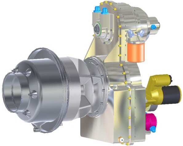
Figure 1
The Mark-17 gearbox contains (a) the startup clutch which allows the engine to start with no load attached, (b) the high-capacity autorotation clutch, (c) the oil system, (d) the accessory drive systems, and (e) the gearing to reduce the turbine's 61091 RPM to 2535 rpm which drives both the main rotor and tailrotor gearboxes.
The Mark-17 begins with the primary reduction which is based on the planetary reduction gears from the Solar APU gearbox, shown in Figure 2. This primary reduction transforms the turbine output (12.9 lb.-ft. of torque at 61091 RPM) to 131.3 lb.-ft. of torque at 6000 RPM.
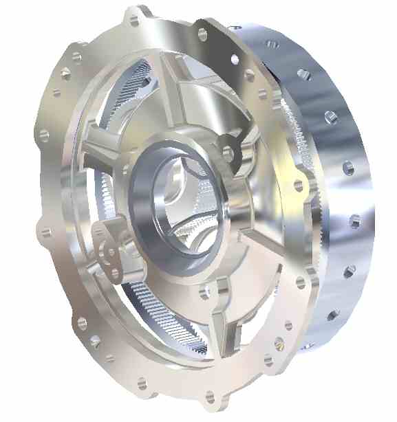
Figure 2
This planetary gearset has a known wear-problem, which occurs when the inner races of the two ball bearings which support each of the 3 planet-gears start to spin on their stationary mounting shafts. That wears metal off the shafts, allows the gears to move out of position, and spreads contaminants through the system.
We developed a clean fix for this problem which we apply to this gearset, along with new planet-gear shafts and substantially higher capacity planet-gear bearings to survive the extended application of high power settings.
We modify the planetary gearset with the addition of a new set of output gears (shown in Figure 3) which implement the secondary reduction, from the primary 131 lb-ft, 6000 RPM primary output to 311 lb.-ft. of torque at 2535 RPM for the EPI Clutch system. This reduction incorporates a high-strength Hy-Vo™ chain which, using the manufacturer's conservative rating system, is good for 8000 hours of operation at this speed transmitting 192 HP.
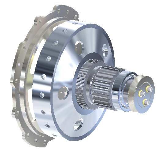
Figure 3
The Mark-17 clutch system, pictured in Figure 4, is a tightly-integrated, turbine startup clutch, autorotation clutch, and oil system. The clutch system shaft provides the drive for both the main rotor and the tailrotor drives.
The startup clutch allows the turbine engine to start with no load, allowing it to accelerate as quickly as possible through the low-RPM, low airflow, very-high-EGT operating range as quickly as possible.
This startup clutch is a multi-disk system which operates in a continuous bath of lube oil to carry away any heat generated during the engagement phase which accelerates the main rotor from rest up to operating speed (520 RPM). It is designed to provide the ultimate in clutch reliability. When the main rotor is up to speed, the clutch is hydraulically locked, providing zero slippage and a considerable over-capacity.
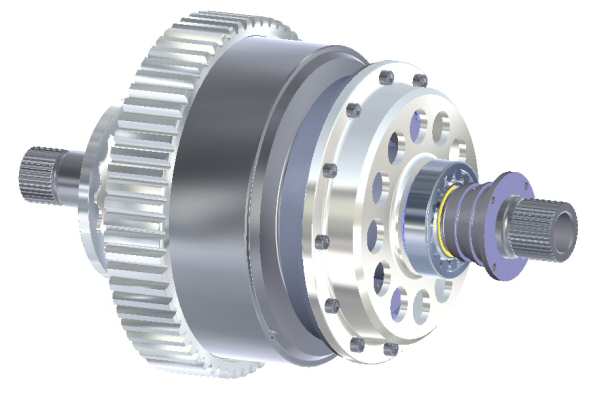
Figure 4
The autorotation clutch is a 24-sprag unit with a diameter over 4 inches, providing a substantially greater capacity than the RotorWay autorotation clutch.
The purpose-designed oil pump provides both lubrication-pressure oil and higher-pressure servo-system oil, along with sufficient over-capacity to provide the cooling function for the main rotor drive (explained in the next section).
The oil pump contains an integrated pressure regulator which maintains the output oil at servo pressure. The pump feeds into the spin-off full-flow 20-micron filter, shown in Figure 5 below, and then to the external air-oil heat exchanger on the airframe. The return oil from the cooler is split off into servo and lube pressure levels. Servo pressure goes to the clutch control and lube pressure goes to the gearbox and main rotor drive heat exchanger.
The oil system also contains a chip detector (the silver-copper-colored thing under the dipstick) which will be wired to an annunciator light on the instrument panel.
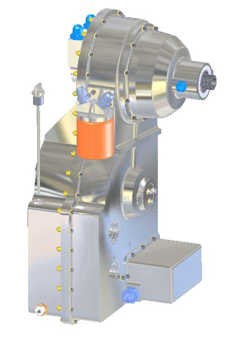
Figure 5
These systems are then installed into the purpose-designed gearbox housing to become the power unit system. The gearbox sump contains a 5-quart supply of turbine lube oil, and has a screw-in dipstick (like a Lycoming) for checking quantity. The oil pump draws from this sump through a removable finger screen which removes shrapnel from the oil.
The accessory-drive contains geared systems to provide for a high-power, lightweight starter which can spin the turbine up over 15% and a contemporary high-grade fuel pump to replace the native pump on the Solar, for which we have been unable to locate a source for parts, as shown in Figure 6.
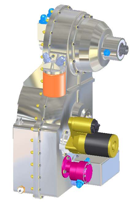
Figure 6
The last accessory, shown in Figure 7, is an integrated, 70-amp lightweight alternator which is driven by a conventional, reliable v-belt system. The mounting provides for easy belt adjustment and replacement.
The output to the main rotor drive is the splined shaft shown in Figures 5, 6 and 7. It uses a short driveshaft to connect to the Mark-18 Main Rotor Drive Gearbox, using torsionally-compliant joints at both ends of the shaft.
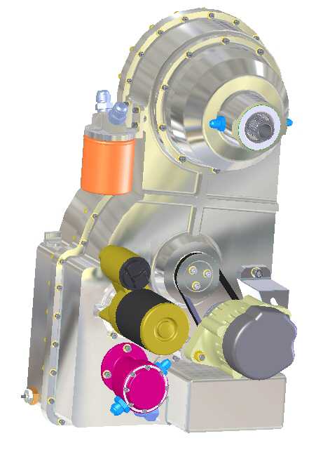
Figure 7
The tailrotor output is on the same axis at the rear of the gearbox, over the engine (shown in Figure 1) and uses a CV joint to drive the segmented tailrotor driveshaft, carefully designed to avoid critical speed divergence and torsional resonance issues.
Note that the airframe-attachment points are not shown in these pictures. They are awaiting final design, and will be completed when an accurate 3D-CAD model of the airframe is completed.
