- Reduction Gearbox for AVL Dyno -
Extends the Useful Range of an Existing Active Dyno System
NOTE: All our Products, Designs, and Services are SUSTAINABLE, ORGANIC, GLUTEN-FREE, CONTAIN NO GMO's, and will not upset anyone's precious FEELINGS or delicate SENSIBILITIES
Background
The testing of the performance characteristics of race engines has become increasingly more complex and sophisticated in recent years, especially at the top levels of motorsport.
In the not-too-distant past, the engine testing program for many racers consisted of a few "pulls" on a passive engine dynamometer ("dyno"). A "passive" dyno is one which basically consists of (a) a power absorber (water brake, hydraulic brake, eddy current brake, etc.) and (b) some rudimentary form of control system which varies the resistance of the absorber so as to just match the torque being produced by the engine (for a steady-rpm run) or which varies the absorber load so as to allow a preprogrammed engine acceleration rate (100 rpm/sec, 200 rpm/sec, etc) over the span of a preprogrammed rpm range (known colloquially as a "pull").
The imposition of stringent emissions requirements on motor vehicle engines created a need for more sophisticated engine testing, and caused the OEM's to develop highly sophisticated real-time combustion analysis systems and sophisticated "active" dynamometers.
An "active" dyno is a system in which the absorber is typically a motor-generator with a permanent-magnet-rotor, and is controlled by a powerful computer-based system which allows test engineers to define and execute complex combinations of test parameters. This type of dyno provides far greater capability for comprehensive and exhaustive engine testing than does a passive system.
An active dyno can (a) be driven by the engine and measure engine torque and RPM, (b) drive the engine and measure the driving torque and RPM, and (c) do combinations of those operations. By using preprogrammed schedules, the dyno can simulate full or part-throttle accelerations, upshifts, long runs at full power, closed-throttle decelerations, downshifts, and various combination.
Race engine developers use those capabilities to accurately simulate lap after lap around a given race course, thereby testing the actual usage which a race engine experiences throughout practice, qualifying and running an entire race.
Almost all OEM's and many top level teams in motorsport (NASCAR, IndyCar, F1, Moto-GP, etc) use complex, environmentally-controlled engine test cells equipped with active dynamometers. The German company AVL is one of the highly regarded suppliers of active dyno equipment. As you might expect, the cost of these systems (depending on your frame of reference) can be staggering.
The Problem
Recently, one engine company, well-known worldwide for its achievements in the design and development of race engines for the Indianapolis 500, for IndyCar and for Formula One, was faced with the prospect of having to replace its existing active dyno with one having higher RPM capabilities in order to do the development testing on a new race engine which operates at significantly higher RPM than their existing AVL dyno was capable of handling.
The following curve shows the max steady-state capacity of the existing AVL dyno (dark lines) is 800 HP (600 KW) between 7000 and 9000 RPM, with transient excursions up to 900 HP (675 KW) allowable for short durations (light lines). While the steady-state power capacity of the dyno was adequate for the task, the operating range of the engine is substantially beyond the dyno's 9000 RPM maximum-speed-for-maximum-power limit.
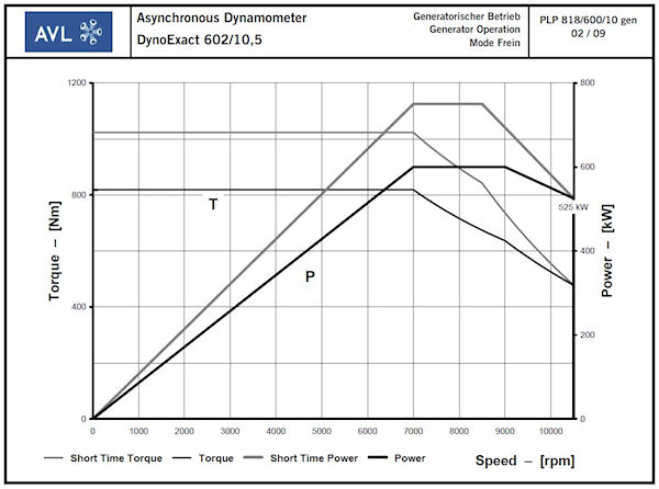
Dyno Capacity Curve
The Solution
That engine company contracted with EPI, Inc. to design and manufacture a gearbox suitable for extended operation at high power levels which would allow their existing AVL dyno to be used within its existing power and speed range while doing complete race simulations on the new, much higher RPM engine.
There were several challenges to achieving a suitable design, including (a) maximizing the efficiency of the gearbox, (b) designing gears that would provide suitable capacity and extremely long life, while being driven by either the engine or by the dyno, (c) designing torsional isolation sufficient to remove the various orders of engine excitation, (d) selecting rolling element bearings which could sustain both the applied loads AND operate at extremely high speeds, (e) lubricating those very high speed bearings, and (f) removing the heat generated during sustained operation.
The customer also required that the gearbox contain an integrated torque measurement system so that gearbox losses could be separated from the dyno's engine performance measurements.
The gearbox system components are manufactured using high-grade materials appropriate to the task of each component, sophisticated manufacturing techniques, and well-developed heat-treatment, surface coating and surface processing technologies.
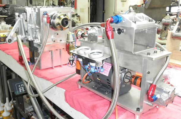
The system contains a stand-alone lubrication module comprising a motor, pump, inlet filter, output filter, heat exchanger, and instrumentation. The gearbox is lubricated and cooled by means of high velocity oil jets to lubricate and cool the gears and bearings, a heat exchanger in the oil system, and radiant / convective cooling by the aluminum housing components.
The following pictures show a few of the features of this system.
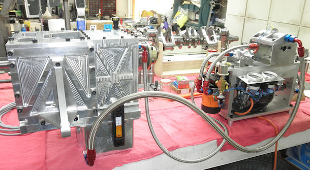
Gearbox and Lubrication Module, Side View
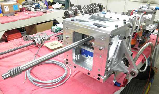
Gearbox and Lubrication Module, Front Quarter View
Gearbox and Lubrication Module, Rear Quarter View
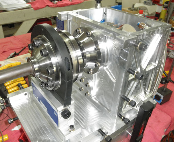
Integrated HBM Torque Sensor
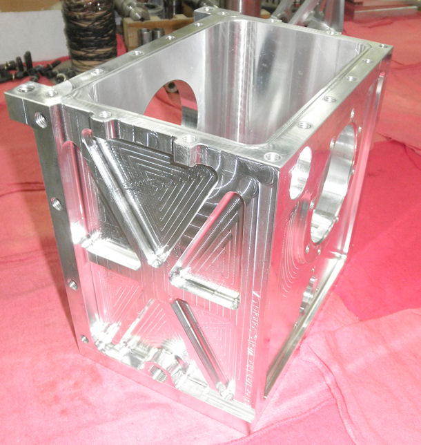
Gear Housing, CNC-machined from a solid brick of high-grade aluminum alloy, by Burhoe Machine Works, Sonora CA, working solely from 3D-CAD solid model files from EPI.
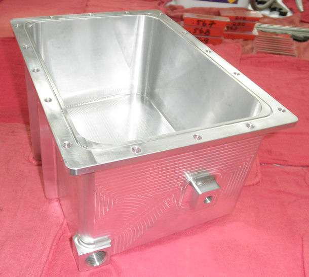
Sump Housing, CNC-machined from a solid brick of high-grade aluminum alloy, by Burhoe Machine Works, Sonora CA, working solely from 3D-CAD solid model files from EPI.
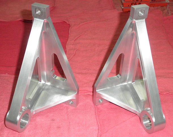
Mounting Arms, CNC-machined from a solid brick of high-grade aluminum alloy, by Burhoe Machine Works, Sonora CA, working solely from 3D-CAD solid model files from EPI.
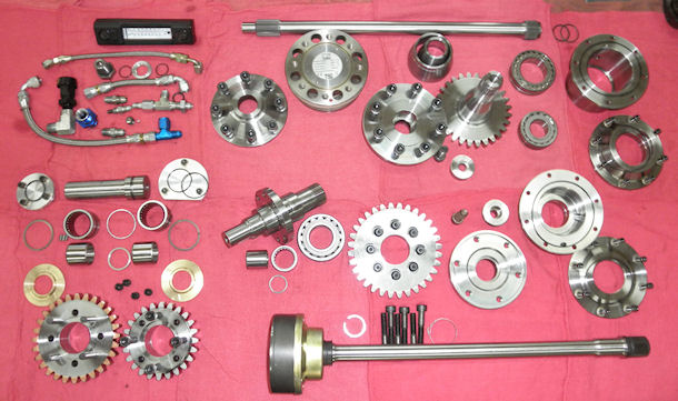
Internal components, most of which were machined at EPI. Specialized operations such as spline and gear hobbing, heat treating, surface processing, and coatings were done by proven-high-quality vendors.
CLICK ON THE IMAGE FOR A LARGER PICTURE
