- Main Rotor Chain Drive -
Power Transmission Properties
NOTE: All our Products, Designs, and Services are SUSTAINABLE, ORGANIC, GLUTEN-FREE, CONTAIN NO GMO's, and will not upset anyone's precious FEELINGS or delicate SENSIBILITIES
ROLLER CHAIN DRIVES: GENERAL INFO
A roller chain system is typically analyzed using zero preload. Here's why. When first installed, a roller chain drive may be adjusted to achieve a certain preload. However, after it has run a short while, roller chain stretches. The initial preload is intended to compensate for the initial wear and prevent the chain from being too loose after that initial wear occurs. In general, there is little-to-no residual preload after a brief run-in period.
With zero preload, there are only two forces at work in the chain drive: (1) the chain tension produced by the transmitted torque, and (2) an additional tension force generated by the centrifugal force of the chain going round the sprockets. The centrifugal force is evenly distributed along the chain. (Centrifugal force also exists in belts, but is usually quite small because the weight-per-foot of belts is considerably less than the weight of a chain with similar transmission capacity.)
The centrifugal component of the chain load becomes a limiting factor as the pitchline velocity of the chain gets large. The chain can only carry a certain total tensile load, which is the sum of the driving tension and the centrifugal tension. Clearly, as the centrifugal component gets large, the allowable driving tension must decrease in order for the sum to be within the limit, which reduces the maximum allowable torque. In the case of the RotorWay secondary drive, the centrifugal force component is relatively small (less than 100 pounds).
One advantage of a chain system is the fact that, at a constant speed, the bending load which the chain applies to the system shafts is proportional to the torque being transmitted. A constant-speed belt system, by contrast, always applies the same (maximum) bending load to the shafts, regardless of the power being transmitted.
THE ROTORWAY CHAIN SYSTEM
The Rotorway-supplied drive mechanism to transmit power from the secondary shaft to the main rotor shaft is a 3-gang roller chain. It is a heavy-duty version of an ANSI-50-3 chain, having side link plates which are about 14% thicker than the standard -50 chain (0.092 vs. 0.080).
The chain we examined was manufactured by Oriental Chain Manufacturing (OCM). It is claimed to have several features which enable it to carry more load than the chain of other manufacturers. We were unable to get ANY response to several requests for technical data from OCM regarding their chain product. Therefore, in the analysis, we used specs for an Emerson 50-3 chain, suitably adjusted to take the thicker side-links into account.
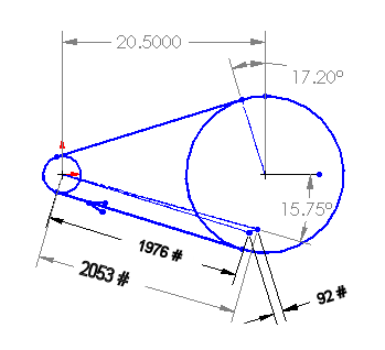
The following diagram shows the pertinent data for the Rotorway main rotor chain drive in the Max Power condition (transmitting 123 HP to the main rotor). The dotted lines represent scaled force vectors, showing the driving and centrifugal forces as applied to the secondary shaft. The diameters shown in the sketch are the standard pitch diameters for 50-series sprockets having 19 and 80 teeth respectively. The center distance is calculated from those diameters and a chain with 118 pitches.

Chain Drive at Max Power
Although the chain weight is significant (2.327 lbs. per foot), the pitchline velocity at 2168 RPM is relatively low (2155 ft. per minute) so the centrifugal force component is only 92 lbs. The driving tension produced by the maximum main rotor power (123 HP, or 298 lb-ft of torque at 2168 RPM) on the 19-tooth driving sprocket (3.797 pitch diameter) is 1884 pounds.
The tight side chain tension is the sum of the driving tension and the centrifugal load (1976 lbs.) The slack side tension is the centrifugal component only. The resultant shaft bending load is 2053 lbs. at an angle of 15.75 degrees as shown in the sketch.
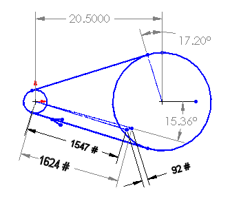
Now at the cruise main rotor power (95 HP, or 230 lb-ft of torque at the same 2168 secondary RPM), the driving tension is only 1455 pounds. The chain speed is the same, so the centrifugal component is the same 92 pounds, and the tight side chain tension is 1547 pounds. The resultant bending load is 1624 pounds. That condition is shown in the sketch below.

Chain Drive at Cruise Power
DYNAMIC FACTORS
Using the stretch modulus of the chain and the pitch diameter of the driving sprocket, it is easy to calculate that the effective torsional rate of the chain drive is about 383 lb-ft per degree.
Because the chain weighs about 14.3 pounds and travels at the outer diameters of the sprockets, it makes a significant contribution to the mass moment of inertia of the sprockets. For dynamic modeling purposes, the portion of the chain actually in contact with each sprocket was included in the calculation of the sprocket Jm. The chain mass of the two spans was assigned to the sprockets in proportion to the reduction ratio.
Observations about the chain drive not specifically related to this analysis:
- In this application, the chain is very highly stressed, and its fatigue life is severely limited. That fact is confirmed by the factory recommendation that the chain be replaced every hundred hours of service. We concur, and would not consider running it one second beyond 100 hours. (Truth be told, we'd probably replace it sooner.)
- Many builders have observed that the fiberglass enclosure required to keep the chain lubricated (a) frequently leaks, and (b) blocks the inflow of cooling air to the heat exchanger.
- A few builders are known to have experienced the spontaneous disassembly of the chain master link in flight.

