- RotorWay Engine Issues -
Valvetrain Problems, Startup Problems, Overall Reliability
NOTE: All our Products, Designs, and Services are SUSTAINABLE, ORGANIC, GLUTEN-FREE, CONTAIN NO GMO's, and will not upset anyone's precious FEELINGS or delicate SENSIBILITIES
There are five Engine Concern subjects covered on this page:
- BAD Practices with New Engines
- Engine Valve Train Issues
- Cylinder Head Design
- Potential Engine Improvements
- EPI Engine Development Program
1. BAD PRACTICE with NEW ENGINES
Recently we ran across a potential source of problems regarding valve lash instability. It seems that many builders like to remove the spark plugs and spin the engine on the starter to see if the oil pump can still make pressure. We saw one account of a guy doing that every month for the duration of his assembly project.
It cannot be stated too emphatically: THAT IS A BAD PRACTICE. Here's why.
This graph shows the contact stress at the cam-lifter interface at 800 RPM and 4800 RPM for an engine with a good cam-lobe design and using a low seat-load valve
spring. The contact stress at idle is the dark line, and the contact stress at high speed is the green line.
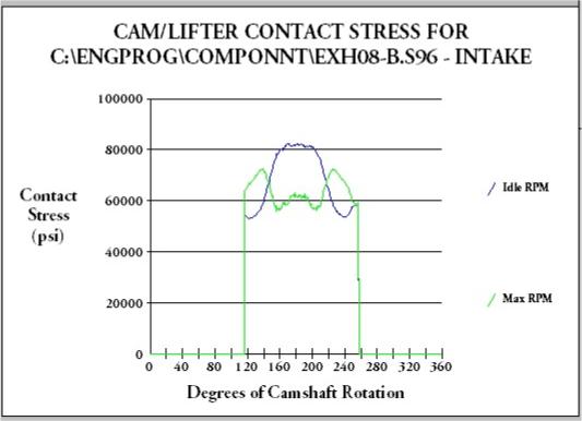
Valvetrain Contact Stress Levels
Notice that the contact stress between the lifter and the nose (peak) of the cam lobe (blue line) is very high at idle speeds and DECREASES as engine speed increases (green line).
Why is that? As the engine speed increases, more and more of the spring force is being used to provide the negative acceleration required to reduce to zero the speed of the lifter, pushrod, rocker, valve and retainer, so that it can reverse direction at peak lift and keep the lifter in contact with the cam lobe. Therefore the contact stress over the nose of the cam lobe decreases as engine speed increases (shown by the green line in the graph above).
At low speeds, the maximum valve velocity is relatively low, therefore there is not much kinetic energy in the valvetrain motion. When there is less kinetic energy, then less of the valve spring's energy is used to produce negative valve acceleration (slow the components down to zero velocity over the nose of the lobe), so more spring pressure is available to be applied to the cam-lifter interface. To make it worse, while the engine is being cranked by the starter, there is virtually no lubrication at that interface. (see Valve Train Dynamics in the Engine Technology section).
The first startup of a new engine is very critical in terms of establishing whether or not the valve train will be stable, or even survive the first few hours of operation.
In order to assure a successful break-in of the cam-lifter interface on all our newly-built flat-tappet (i.e. non-roller) engines, we
- Mirror-polish the bottoms of all the lifters prior to installation,
- Apply copious amounts of molybdenum-disulphide lubricant to all cam lobes and to the bottom of all lifters,
- Pre-oil the entire engine with an external drive on the oil pump (not by turning the engine) or with an external pump when the oil pump drive is not accessible.
In order to assure an instant first start (i.e.: MINIMAL cranking on the starter) we:
- make absolutely sure that the spark is correctly set, and
- make absolutely sure that the fuel delivery system (FI or Carb) is primed and capable of delivering fuel RIGHT NOW.
When we start a newly-built "flat-tappet" engine for the first time, we never let it run lower than 2000 RPM for the first half hour, assuring good lubrication to the lifters and reasonably low contact stresses throughout the entire lift profile.
If the valve train is really radical (an aggressive, high-RPM cam and spring pressures of 250 pounds on the seat and 600 pounds over the nose, for example), it is very likely that a a "flat-tappet" cam and lifters will not survive the initial startup. On those engines, we install a special set of valve springs (much lower pressure) just for the first half-hour run (lobe-to-lifter break-in) and then install the heavy springs.
2. VALVE TRAIN ISSUES
Early in our research into RotorWay helicopters, we were surprised to discover that operators are required, by factory instructions, to do an extensive valve train inspection and adjustment procedure every 25 hours of operation. We were even more surprised to discover that the RW engine uses solid lifters and lash caps in the valve train.
The required inspection calls for
- Checking valve-to-rocker clearance ("lash") but, quite unbelievably, also requires
- Looking for evidence that the keepers are pulling through the spring retainers ( ! ) and
- Looking for signs that the lash caps are being pounded into mushrooms.
Based on discussions we have had with a few current owners, those procedures appear to be VERY essential. The frequency of required adjustments suggest that the valve train can be on a short track to self destruction.
We offered to work with the factory to solve these problems, but as usual, their answer was "There are no problems with the valve train".
Since 1970, there has been a nearly-universal adoption of automatic lash compensation ("hydraulic lifters") in automotive and truck engines. Further, all the Lycoming 320, 360, 540 and 720 engines use hydraulic lifters (and probably all the Continentals too; Don't know for sure). The Orenda V8 uses hydraulic lifters. The EngineAir V8 uses hydraulic lifters. The EPI Aircraft V8 uses hydraulic lifters.
In addition to automatic compensation for changes in engine dimensions (which, if uncompensated, would change the lash, hence certain critical engine operating parameters), hydraulic lifters also act as absorbers of certain high levels of shock imparted by aggressive cam profiles.
It seems quite inconceivable that RotorWay would claim there are no problems with a valve train which:
- Needs lash caps to prevent the valve tips from being destroyed by the rocker arms,
- Experiences ever-increasing valve lash,
- Experiences ever-decreasing clearance between the edges of the lash caps and the spring keepers,
- Experiences broken valve springs,
- Experiences keepers pulling through the spring retainers, and
- Requires that the camshaft drive gear be replaced at 250 hours (if it actually lasts that long).
These symptoms are compelling evidence that one or more of the following design problems exist:
- The cam lobe profile contains an extremely harsh and uncontrolled acceleration schedule,
- The valve springs and / or pushrods are vibrating out of control due to excitation from very high harmonic content of the cam lift and acceleration profiles,
- The crankshaft is applying an extraordinary amount of torsional excitation to the valve train, and/or
- The geometry defining the interaction of the rocker tip and the valve stem is terribly incorrect.
(The only engines we have seen which require lash caps are (a) those with titanium valves having no hard insert at the tip or (b) those using a very poor cam design. Also, engines which fail valve springs in mid-coil typically have very poor cam designs and mismatched valve spring designs.)
Several months after writing this initial analysis, we had the opportunity to run a new RotorWay camshaft through our computerized camshaft measurement system. The analysis revealed that the cam lobe design used an ancient practice which attempted to cut a constant-acceleration flat onto the positive acceleration portion of the profile. The RotorWay cam lobe data are shown in the following picture.
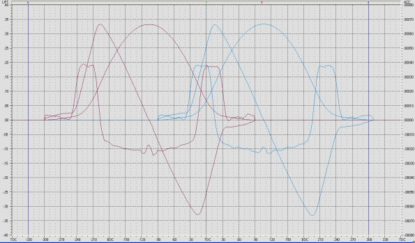
RotorWay Camshaft Profiles
You can see that the "constant-acceleration" flats really are not really constant. But worse is the existence of the very sharp transitions from increasing / decreasing acceleration to the "flats". Those discontinuities in the curve produce some of the most hideous jerk profiles we have seen. ("JERK" is the third derivative of motion and the first derivative of acceleration. JERK shows the level of impact loads in a system.) These large jerk values show the existence of (a) very large impact loads in the system, and (b) high amplitude content of higher-order harmonic excitations.. Also iinteresting in these accel curves is the substantial reversal wave over the nose of the lobe. That flaw can contribute even more high order harmonic excitation, leading to the kind of multiple fractures we have seen in RotorWay valvesprings.
We also did a quick analysis of the buckling resistance and the buckling resonant frequency of the RotorWay pushrods. That revealed yet another flaw in the design. The pushrods go into buckling deflection at relatively low loads, and the resonant frequency is low enough to be quite near the operating points of the engine.
No wonder the valve train comes apart.
3. CYLINDER HEAD
Without cutting a casting apart, it is hard to tell, but from the outside, it looks as if RW did a good job with the placement of coolant around the exhaust valves and with the flow-velocity distribution inside the head.
The combustion chamber, however, could benefit significantly from some current technology.
The existing combustion chamber looks extremely similar to that of an early Small Block Chevy V8 (SBC), and has dual spark plugs fitted.
Unfortunately, the side-by-side location of the two plugs accomplishes redundancy, but does little to achieve the power and detonation margin ("mechanical octane") increases available from a high-quality combustion chamber with well-located dual plugs.
The study of sequential combustion events shows that the peak combustion pressures in a sequential series of combustion events fall into a skewed distribution, with a small percentage of misfires and slow-fires. Those tests demonstrate a high probability of ignition, all other things being correct.
Spark plugs located adjacent to each other (such as in the RotorWay design) provide no more than a slight improvement in the already-relatively high probability of ignition. EPI has proven that fact in dyno-tests of the Phase-1 Dual Plug cylinder head we used on our first aircraft V8 (pictured on our HOME page), which had side-by-side dual plugs like the RotorWay .
The additional benefit which a proper combustion chamber would provide is a significant increase in detonation margin, which would yield more power and greater reliability at the same time (a truly rare combination).
4. POTENTIAL ENGINE IMPROVEMENTS
At the RW-claimed output of 150 HP, the existing RW-162 engine would operate at a BMEP of 175 psi. (Brake Mean Effective Pressure, Engine Technology Section). The existing general configuration of the RW intake system is conducive to the production of high BMEP. Our calculations show that 200 psi should be achievable with a good cylinder head and matched intake system, which would produce over 170 HP at 4200 RPM, and over 180 HP at 4500 RPM. For comparison purposes, our normally-aspirated aircraft V8's reliably produce a BMEP over 218 psi. (more than 1.44 lb-ft of torque per cubic inch of displacement).
If the RW engine produced 170 HP at full throttle in standard day condotions (59°F, 29.92 Baro), it could easily be flat-rated back to 150 HP by limiting the MAP to approximately 27.7". That would provide safe operation at much higher density altitudes than now possible.
Incidentally, that's exactly what they do in the Schweitzer 300C. The Lycoming IO-360-D1A engine has the high-flow angle-valve heads, larger intake tubes, a larger Fuel Injection servo (Bendix RSA-7), 10:1 compression pistons, and runs at 3200 RPM. At 29.5" MAP it can make around 240 HP, but it is flat rated to 190 HP by limiting the MAP to 26".
5. ENGINE DEVELOPMENT PROGRAM
Because EPI has the experience, the equipment and the technology to analyze and cure the valve train problems (see EPI Services), as well as considerable experience in the development of high performance engines and cylinder heads, in 2003 we considered doing a development program on this engine to address the valve train reliability issues and to increase the power output by means of a high-quality cylinder head and other enhancements.
The upgrade program would have included at least the following processes:
- removing the engine from the airframe,
- crating and shipping the engine to EPI,
- EPI teardown and IRAN (Inspect and Repair As Necessary) of the engine,
- EPI replacement of the camshaft, lifters, pushrods, cylinder heads, rocker system, and other engine parts with properly designed components,
- EPI rebuild of the engine,
- EPI recalibration of the FADEC or carburetors,
- EPI dyno-test of the engine,
- EPI crating and shipping back to the customer,
- reinstallation in the airframe,
- producing an installation and operation manual, and
- ongoing support of the product.
Considering all those program steps, a thorough analysis of the cost to upgrade a customer's engine leads to the inescapable conclusions that because of the high cost, there would be virtually no market for the upgrade. Further, the potential reliability problems with other flaky parts of the engine, coupled with RotorWay's intransigent NIH attitude, made it clear this engine upgrade project was a definite loser.
Therefore, EPI has no plans to do any further work on the RW piston engine.
