
- Engine Mount Structure Design -
Critical Elements and Procedures
NOTE: All our Products, Designs and Services are SUSTAINABLE, ORGANIC, GLUTEN-FREE, CONTAIN NO GMO's, and will not upset anyone's precious FEELINGS or delicate SENSIBILITIES.
EPI, Inc. does design and analysis of engine mounts for the installation various engines (liquid-cooled and air-cooled piston engines and turboprop engines) into both certified and experimental aircraft.
Some examples of our work are shown in the Spacewalker-II design project, the 434-CI Small Block Chevy-on-GP-5 Reno Racer project, the 572 CI Big Block Chevy-on-Air Tractor 301 project, the Orenda-on-Air Tractor 401 project, and the Orenda-on-Aero Commander 685 project.
Here is a 3D-CAD example of one of our mount designs.
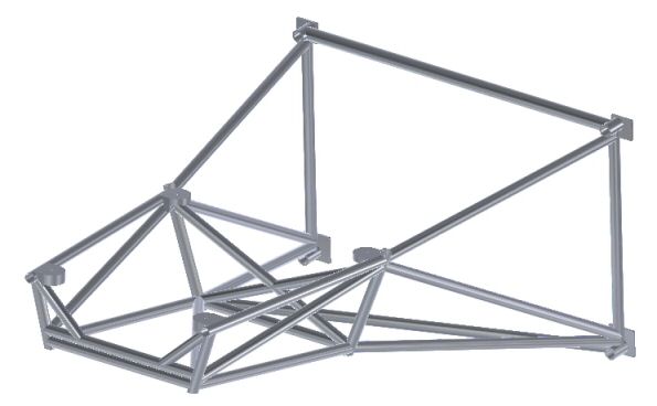
Sample V8 Engine Mount Structure (572 Big-Block onto Air Tractor-301)
Design Process
The first order of business in engine mount design is to determine the initial physical mount configuration. That initial design work depends upon certain basic information, including accurate (3D-CAD when available) definitions of:
- the firewall pickup points,
- the engine attachment points,
- the powerplant top, front, rear and side profiles (a 3D CAD engine model is even better),
- the desired location and orientation of the propeller centerline,
- the top, front and side fuselage profiles (a 3D CAD engine model is even better),
- the desired cowling profiles (a 3D CAD engine model is even better),
- the locations and sizes of the other physical components which will be needed (such as coolant heat exchanger, plumbing, exhaust system, turbocharger, intercooler, engine inlet air ducting, alternate air system, remote oil filter, fuel filter, oil cooler, etc. etc. etc.).
- the weights and CG locations of the major components to be supported by the mount structure (powerplant, propeller, turbocharger, heat exchangers, etc.),
- the operating points and mass moments of inertia of the rotating components (propeller, engine and PSRU rotating assemblies, turbocharger rotor system, etc.)
Load Analysis
Once the initial mount design is established, the next step is to determine whether the structure can support the loads it will see in service, with an adequate safety factor.
For certificated aircraft, the Federal Aviation Regulations provide a comprehensive set of design criteria. These minimums, provided in 23.361 (engine torque effects), 23.363 (side loads on engine mount), and 23.371 (combinations of gyroscopic and aerodynamic loads) provide good guidance for experimental designers as well.
The loads a powerplant applies to its mounting structure can be classified into two categories:
- "g" loads (vertical and horizontal) and
- flight condition loads (torque, thrust, and gyroscopic moment).
In order to calculate the "g" loads (loads resulting from vertical and horizontal accelerations encountered in flight) which a particular powerplant applies to the engine mount pickup points, you must first know the weight and CG location of all the components which the mount must support.
EPI developed a computer program to determine the weight and CG location of the powerplant and all items attached to it, as well as for specific separate subsystems attached directly to the motor mount. Naturally, the accuracy of the results depends on the accuracy of the weights and locations ( x, y and z coordinates ) of the components.
With that information, and a list of the flight conditions to be investigated, we go on to the next EPI computer program which calculates the loads which the powerplant applies to its mount structure during user-defined flight scenarios. The input parameters are :
- Power and RPM,
- Direction of Engine and Prop Rotation
- Thrust OR Propeller efficiency,
- Vertical and Horizontal g-forces,
- Pitch and Yaw rates,
- "P-Factor",
- Thrustline cant-angle and tip-angle,
- Engine Mounting-Point geometry and stiffness.
From those inputs, the program calculates the 3-axis loads and moments which the engine applies to the mount structure as a result of the specified combination of input parameters.
The analysis takes into account the horizontal and vertical g-loads for the specific scenario, the torque and thrust generated by the propeller, the thrust offsets resulting from flight at high angles of attack as well as from thrustline geometric offset, and the combined gyroscopic effect of the engine and propeller.
The program also compares the calculated 3-axis loads and moments against the Engine Manufacturer's limit specifications, and flags loads which exceed those limits.
Stress Analysis
The resulting loads and moments are used in a Finite Element Analysis (FEA) package to determine the combined stresses generated in each element of the engine mount structure as well as the loads the engine mount assembly applies to the airframe in the flight condition being studied. We also use the FEA tool to determine the vertical and horizontal stiffnesses of the structure, to be sure there is adequate separation between the horizontal and vertical resonant frequencies (see whirl mode).
If any of the stresses exceed design limits, the mount design is altered and the analysis for that scenario is run again. This process continues until the design meets the prescribed design limits.
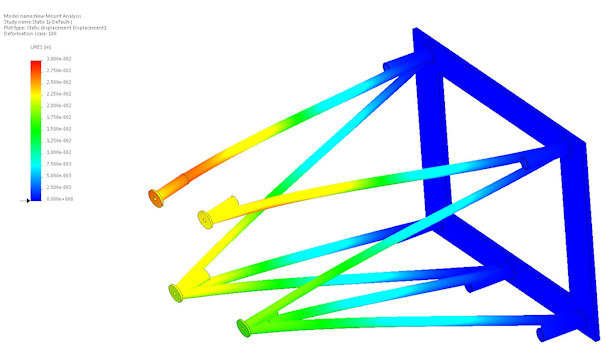
FEA Output for one load scenario
When the mount design is satisfactory, it is sensible to examine the loads that the new powerplant installation will apply to the airframe. Those loads, determined during the mount structural analysis, can be used as input to another FEA application to determine whether the existing airframe structure is adequate, and if not, to determine if the proposed modifications to the aircraft structure are satisfactory.
When a satisfactory mount design and analysis have been completed, EPI can also prepare test plans for submission to the FAA, and can execute an approved mount test program.
Fabrication
EPI no longer does fabrication work. However, in the past, we had the in-house fabrication capabilities to construct prototype mounts from mild steel or from alloy steel (4130, etc.) tubing, including fixturing, comprehensive machining facilities, and GTAW ("heli-arc") welding facilities. If a client is interested, we can refer him / her / it to a highly qualifed and skilled fabricator in the Southwest Washington area (who builds mounts for a major Kitplane manufacturer).
After the design and analysis is complete, it is necessary to build some form of fabrication fixture which duplicates the essential features of the aircraft firewall and which locates the engine pickup points in 3D-space with respect to the firewall and fuselage attachment points. (see picture above). The basic time and materials estimates for that process is 20 to 30 hours and about $500 - $1000 in materials.
An accurate engine mock-up is also required. If an engine mock-up is not available, then an additional fixture which duplicates the engine pickup points must be fabricated. That task can consume an additional 10 to 15 hours and another $300 - $600 in materials.
The time and materials required to fabricate the mount itself are entirely dependent on the mount design and geometry. Complex mounts have consumed as much as 50 hours to fabricate.
Here is a picture of the mount shown above in the 3D-CAD view, for one of our cropduster conversions, still in the fixture, after being fabricated from 4130 steel tubing in our shop. The mount weighs 53 pounds, and supports all the FAA combined loads from a 750 HP, 1235-pound V8 powerplant with a comfortable margin. The little hose at the front of the mount structure is for replacing the air and moisture inside the tubes with argon, in order to preclude invisible corrosion from the inside-out.
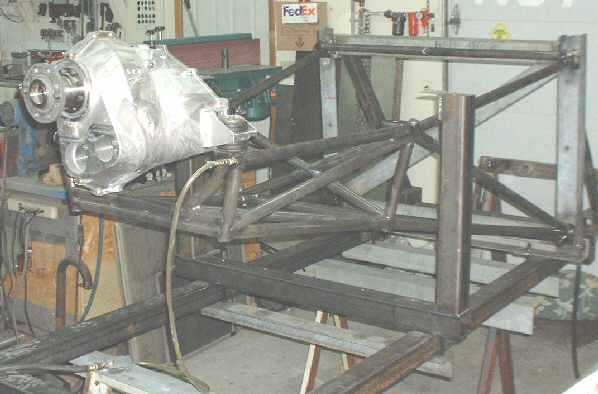
V8 Mount in Fabrication Fixture
This picture shows that same mount in the fabrication fixture, with the full powerplant installed.
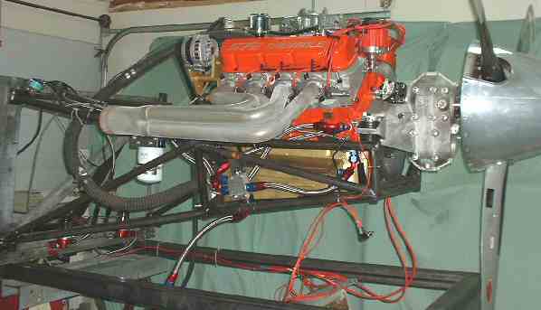
V8 Mount with Complete Powerplant
Costs
We receive frequent inquiries regarding the design and construction of one-off mount structures for various new aircraft, kits under construction, and engine conversion projects. Here is the breakdown of a basic cost estimate to design and build such a prototype structure.
It typically takes between 10 and 20 hours for us to engineer and design a good mount structure. That estimate presumes that the client can provide all the data described above under the Design Process heading. Otherwise, there is additional effort required to establish the design parameters.
Our current billing rate is $125 per hour, plus materials at cost. The total cost for design and fabrication of a one-off custom mount is not likely to be less than $5000 (USD).
There are other mount design projects described on this site, in various levels of detail. The most detailed is the Spacewalker-2 design. Also of interest might be the Orenda-to-Areo Commander 685 design, the Orenda-to-Air Tractor 401 design, the 572 CI Big Block Chevy-to-Air Tractor 301 design, and the 434 CI Small Block Chevy-to--GP-5 racer design.
